Device for controlling the phase angle between a first and a second crankshaft

a technology of phase angle and internal combustion engine, which is applied in the direction of engine controllers, yielding couplings, couplings, etc., can solve the problems of reducing affecting the service life of the engine, and requiring a relatively large accommodating space in the axial direction of the pipe element, so as to achieve cost-effective manufacturing

Inactive Publication Date: 2003-06-19
ALVAR ENGINE
View PDF0 Cites 45 Cited by
  • Summary
  • Abstract
  • Description
  • Claims
  • Application Information

AI Technical Summary

Benefits of technology

0008] An object of the present invention is to provide a device for controlling the phase angle between a first and second crankshaft of an internal combustion engine, which, relative to previous technology, is more cost efficient to manufacture.

Problems solved by technology

One drawback is that it is relatively expensive to manufacture it, since it is relatively complex in its design, especially concerning the displaceable pipe element, which is equipped both on the enveloping surface and internally with spiral-shaped splines.
Another drawback is that the pipe element, including the hydraulic control system, needs a relatively large accommodating space in its axial direction.
This makes it difficult to install it in cars with lateral multi-cylinder engines.
Furthermore, assembly / disassembly of this device is relatively difficult to carry out.

Method used


Image

  • Device for controlling the phase angle between a first and a second crankshaft
  • Device for controlling the phase angle between a first and a second crankshaft
  • Device for controlling the phase angle between a first and a second crankshaft

Examples


Embodiment Construction

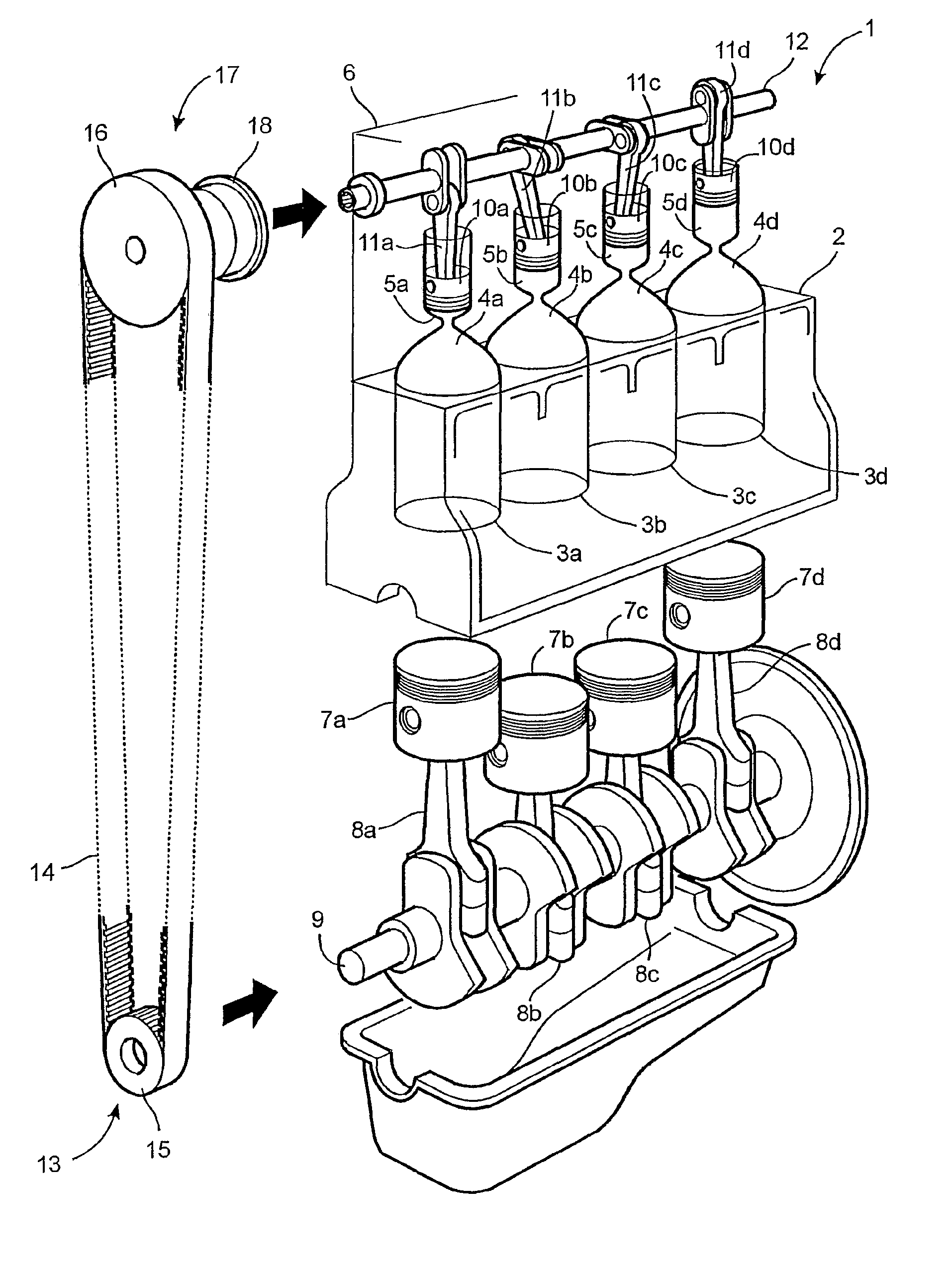
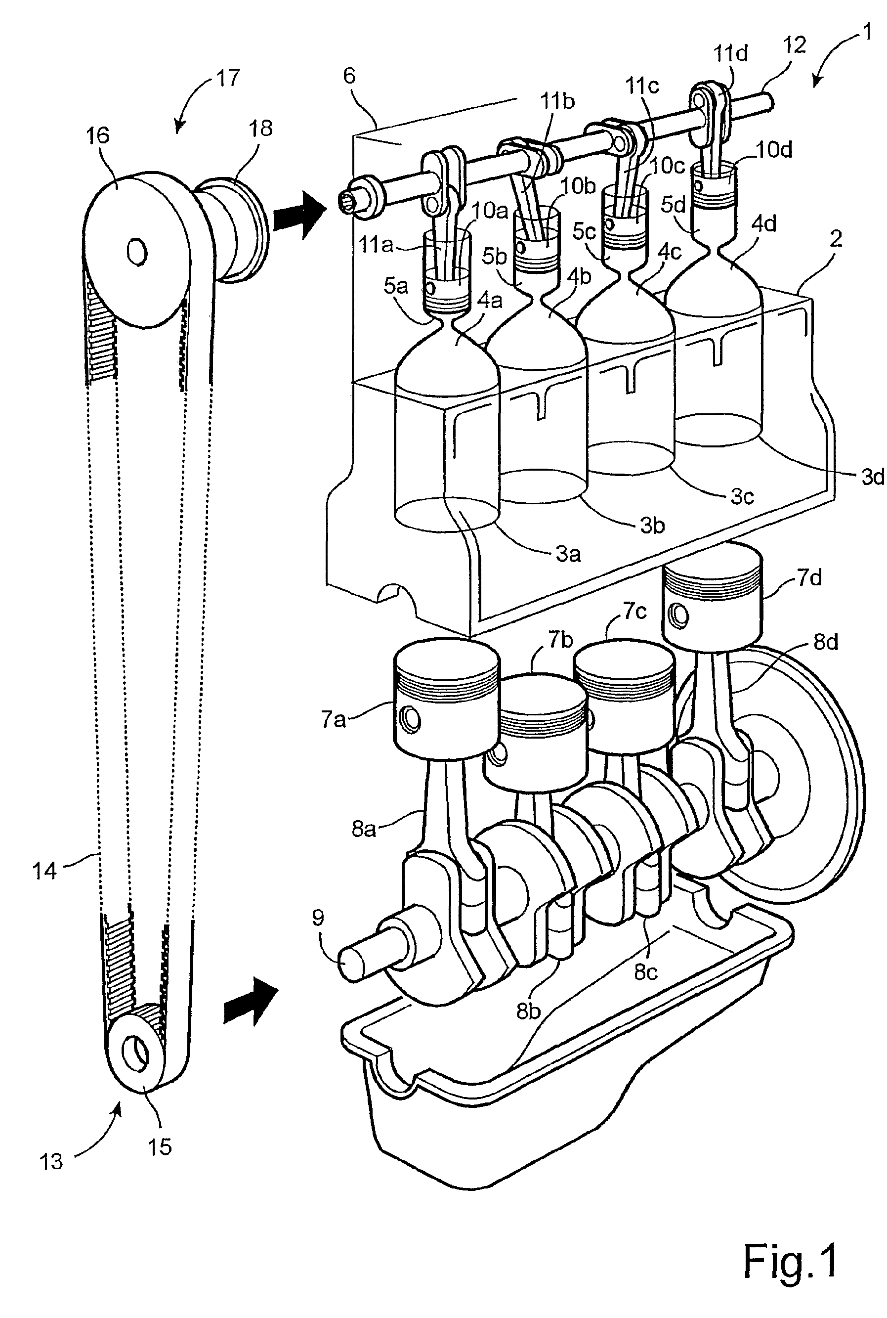
[0019] Fig. 1 shows, in a perspective view in partial cross-section, an internal combustion engine 1 with an engine block 2 with primary cylinders 3a, 3b, 3c, 3d that respectively communicate via channels 4a, 4b, 4c, 4d with secondary cylinders 5a, 5b, 5c, 5d arranged in the cylinder head 6 of the internal combustion engine 1. In every primary cylinder, primary pistons 7a, 7b, 7c, 7d are reciprocatingly arranged and by means of primary connecting rods 8a, 8b, 8c, 8d are connected to a first crankshaft 9. In every secondary cylinder 5a, 5b, 5c, 5d, secondary pistons 10a, 10b, 10c, 10d are reciprocatingly arranged and are connected to the second crankshaft 12 by means of secondary connecting rods 11a, 11b, 11c, 11d. The first crankshaft 9 is mounted in bearings in the engine block 2, and the second crankshaft 12 is mounted in bearings in the cylinder head 6. The crankshafts 9, 12 are connected to each other by means of a transmission 13 that includes a cogged driving belt 14 that runs...


PUM


Abstract

Abstract of Disclosure Method and device for regulating the phase angle between a first and a second crankshaft of an internal combustion engine. The engine includes primary cylinders that communicate with secondary cylinders and in every primary cylinder there is movably arranged a primary piston that is connected to the first crankshaft and in every secondary cylinder there is movably arranged a secondary piston that is connected to the second crankshaft. The first and second crankshafts are connected to each other by means of a transmission adapted with the device that includes a crankshaft extension for obtaining the control of the phase angle, the extension being fixed against rotation and displaceably connected to one of the crankshafts and via a grooved portion rotationally connected to the second of the crankshafts. When the crankshaft extension in displaced, rotation is obtained in the grooved portion that results in a corresponding phase angle shift.

Description

Cross Reference to Related Applications[0001] This application is a continuation patent application of International Application No. PCT / SE01 / 01233, filed 1 June 2001 which was published in English pursuant to Article 21(2) of the Patent Cooperation Treaty, and which claims priority to Swedish Application No. 0002088-3, filed 5 June 2000. Both applications are expressly incorporated herein by reference in their entireties.Background of Invention[0002] TECHNICAL FIELD OF THE INVENTION: The present invention relates to a device for controlling the phase angle between a first and a second crankshaft of an internal combustion engine of the type that includes at least one primary cylinder that communicates with at least one secondary cylinder. A primary piston is normally included that is movably arranged in each primary cylinder and is connected to the first crankshaft. In every secondary cylinder, there is a secondary piston movably arranged that is connected to the second crankshaft. ...

Claims


Application Information

Patent Timeline
Patent Type & Authority Applications(United States)
IPC IPC(8): F02D15/04F16C3/06F16D3/10
CPCF02D15/04F16D3/10F16C3/06
Inventor HALLENSTVEDT , ODDBJORN
Owner ALVAR ENGINE
Why Eureka
Try Eureka