On-vehicle gateway

Inactive Publication Date: 2003-06-26
SUMITOMO ELECTRIC IND LTD
View PDF11 Cites 96 Cited by
  • Summary
  • Abstract
  • Description
  • Claims
  • Application Information

AI Technical Summary

Benefits of technology

0017] It is an object of the present invention to provide an on-vehicle gateway capable of controlling the data to be passed.
0018] It is another object of the present invention to provide an on-vehicle gateway capable of changing the responding method according to the state of a vehicle.
0019] It is st

Problems solved by technology

However, they are problematic in that they also transfer unwanted data, which are undesirable in terms of safety and

Method used


Image

  • On-vehicle gateway
  • On-vehicle gateway
  • On-vehicle gateway

Examples


example 2

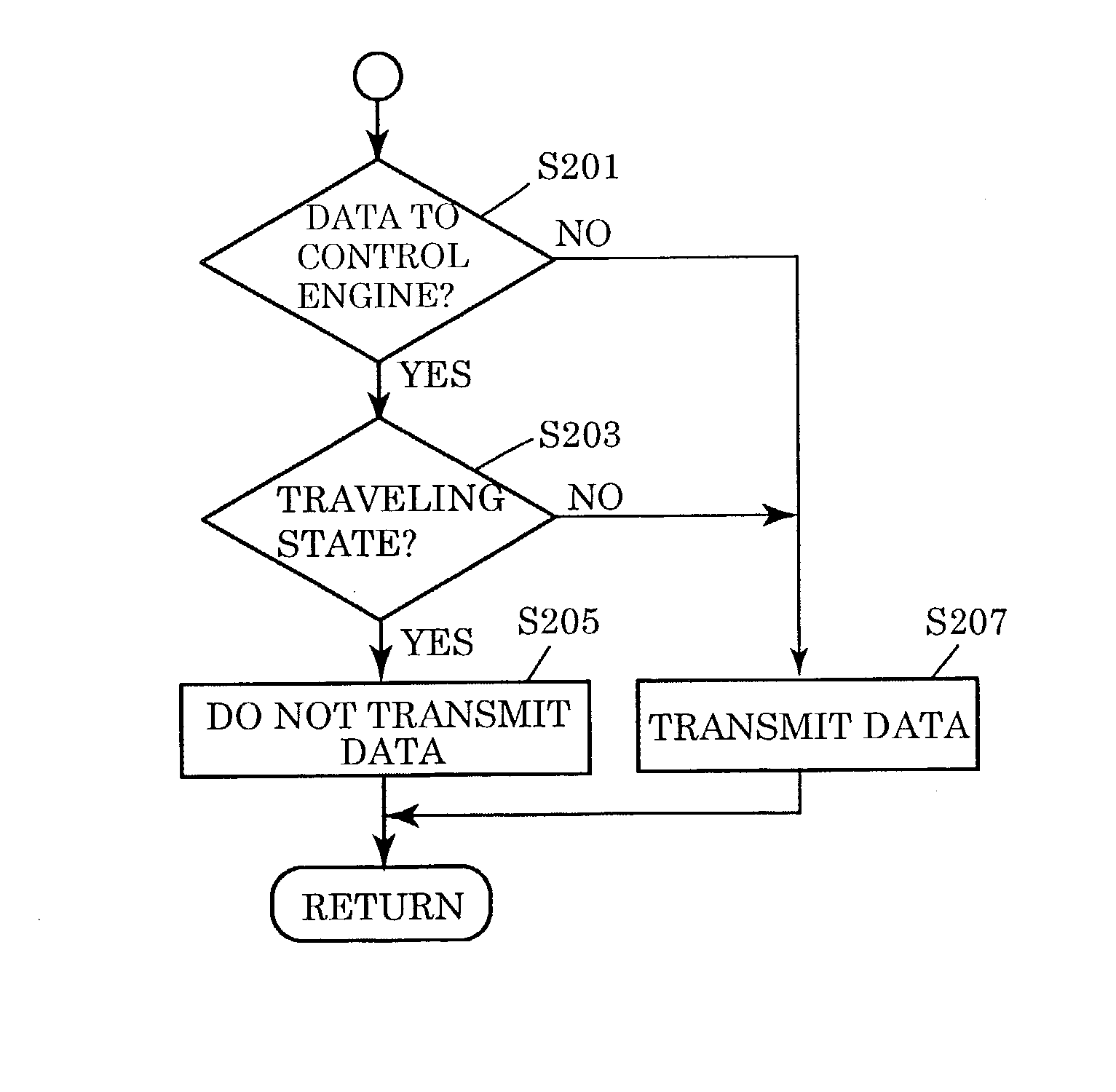
[0084] In the arrangement comprising the bus and the gateway shown in above-described example 1, the gateway to connect the control-system bus and the information-system bus is designed to transfer diagnosis data for detecting failure only while the vehicle is in a stopped state, and not to transfer diagnosis data while the vehicle is traveling. This makes it possible to reduce the amount of data transfer of the information-system bus, and to improve the response of the devices connected to this bus. A similar effect can also be obtained by passing the diagnosis data only when an on-board device is out of order.

[0085] FIG. 6 is a flowchart showing a controlling method for the gateway in this example 2. Step S301 determines whether the vehicle is traveling. If the determination result in step S301 is "YES", step S303 determines whether the data inputted into the gateway are diagnosis data. If the result of determination in step S303 is "YES", the transfer of the data of is not perfor...

example 3

[0087] In the arrangement comprising the bus and the gateway shown in above-described example 1, the filtering policy is changed according to the power supply state. Specifically, different operating devices operate in different power supply states. For example, devices related to traveling state (Anti-lock Brake System (ABS), engine control, transmission control) do not operate unless the ignition (IG) power supply is in an ON-state. On the other hand, an audio device or the like operates even if the power supply is in the state of ACC (i.e., accessory power supply is "ON"). Therefore, the amount of data transferred by the bus can be reduced by cutting down, in the gateway, data packets directed to devices that do not operate according to the power supply state. Also, the battery can be saved by changing the operation of the gateway according the power supply state. Furthermore, by detecting, according to the power supply state, whether a car is in an operating state, and changing ...

example 4

[0088] In the gateway that establishes the connection between the inside and the outside of the vehicle, the data amount transferred from the outside of the vehicle is adjusted according to the presence / absence of an occupant (driver or the like). For example, when downloading map data for navigation from the outside of the vehicle, the amount of data passing through the gateway per unit time is increased while the occupant is absent, and the amount of data flowing over the bus is reduced while the occupant is present, thereby decreasing the traffic amount. The communication response among the on-board devices can be enhanced, proportionally to the reduced traffic amount.

[0089] In this example, when an occupant is absent the car is considered to be not traveling. In this case, even if data is erroneously transferred, the influence thereof will be relatively small. This makes it possible to reduce certification and filtering processings in the gateway, and to increase the transfer ef...


PUM


Abstract

An on-vehicle gateway is provided that is interposed between a plurality of buses for transferring data, and that is capable of performing appropriate control according to situations.(1) Data coming from one bus are analyzed to filter false data and unwanted data not to feed them to the other buses. (2) When the state of an on-vehicle device is inquired, it is controlled according to the state of an IG power source whether the inquiry is to be made to the device or the on-vehicle gateway answers the inquiry by proxy. (3) The response of the gateway is changed according to the place where a vehicle is traveling. For example, control is performed such that, while the vehicle is traveling on a local road, the transmission/reception of a mobile telephone is available by using a hands-free system, and that, while the vehicle is traveling on an expressway, the transmission/reception of a mobile telephone is unavailable even by using the hands-free system. (4) The response of the gateway is changed according to a driver. For example, if the years of driving experience of the driver is within one year, the gateway stops data transfer so that no television screen or navigation screen is displayed during driving, and that the transmission/reception of the telephone by the hands-free system is unavailable.

Description

[0001] The present invention relates to an on-vehicle gateway, and particularly to an on-vehicle gateway interposed between a plurality of buses and used transferring data.[0002] Japanese Unexamined Patent Application Publication No. 3-295397 discloses a multiplex transmitting method using a relay terminal that is located between a high-speed bus line and a low-speed bus line, and that has a protocol converting function. In this method, control data of a power window motor or the like that have been inputted into a local terminal located on the low-speed line, are transmitted over the low-speed bus line. These data are protocol-converted at the relay terminal. Thereafter, the data flow over the high-speed bus line. The data are protocol-converted at another relay terminal, and transmitted over the low-speed bus line up to another local terminal located there. Thereby, a load such as the power window motor or the like comes into operation.[0003] Japanese Patent No. 2906039 discloses ...

Claims


Application Information

Patent Timeline
IPC IPC(8): B60R16/02B60R16/03H04L29/08
CPCB60R16/0315H04L69/329H04L67/28H04L67/2819H04L67/56H04L67/564
Inventor TOKUNAGA, MASAHIROYOSHIDA, SHINICHI
Owner SUMITOMO ELECTRIC IND LTD
Why Eureka
Try Eureka