Method for high dynamic range image construction based on multiple images with multiple illumination intensities

a technology of illumination intensities and image construction, which is applied in the field of image processing in a noncontact gauge measurement system, can solve the problems of poor laser stripe identification in the resulting images obtained by the cameras, high dynamic light intensity levels, and poor reflectivity characteristics, and achieve the effect of increasing the dynamic light intensity range of an imag

Inactive Publication Date: 2003-06-26
GENERAL ELECTRIC CO
View PDF0 Cites 57 Cited by
  • Summary
  • Abstract
  • Description
  • Claims
  • Application Information

AI Technical Summary

Benefits of technology

0006] Briefly stated, the present invention provides a method for increasing the dynamic light intensity range of an image by fusing pixel data from multiple images collected at different levels of illumination to create a single floating-point image representation of an object undergoing measurement.

Problems solved by technology

The surface of many objects include regions which are shiny or dull, or otherwise have poor reflectivity characteristics.
Structured light projected onto these surfaces can result in a high range of dynamic light intensity levels, i.e. dull spots and overly bright spots.
This results in poor laser stripe identification in the resulting images obtained by the cameras.
Furthermore, in some situations, entire image regions which are representative of portions of an object's surface may become corrupted due to under exposure, i.e. the region appears black, or saturation, i.e. the region appears white.
When using photogrametric methods to identify or measure objects in an image, the accuracy with which a salient feature in the image is located is negatively impacted by pixel saturation or pixel noise.
Therefore, to view a scene which has a high dynamic range of illumination intensity, i.e. from dark to light, inexpensive low dynamic range cameras often prove inadequate.
But, in some applications, the use of expensive, high dynamic range cameras is not possible.

Method used


Image

  • Method for high dynamic range image construction based on multiple images with multiple illumination intensities
  • Method for high dynamic range image construction based on multiple images with multiple illumination intensities

Examples


Embodiment Construction

[0015] The following detailed description illustrates the invention by way of example and not by way of limitation. The description clearly enables one skilled in the art to make and use the invention, describes several embodiments, adaptations, variations, alternatives, and uses of the invention, including what is presently believed to be the best mode of carrying out the invention.

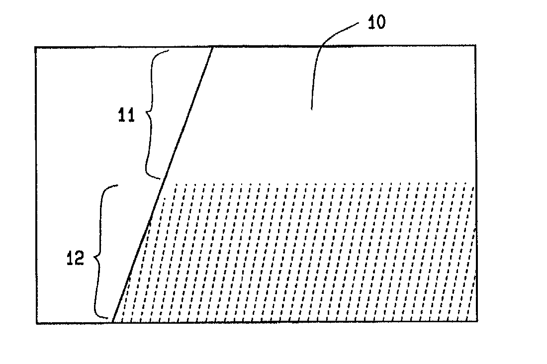
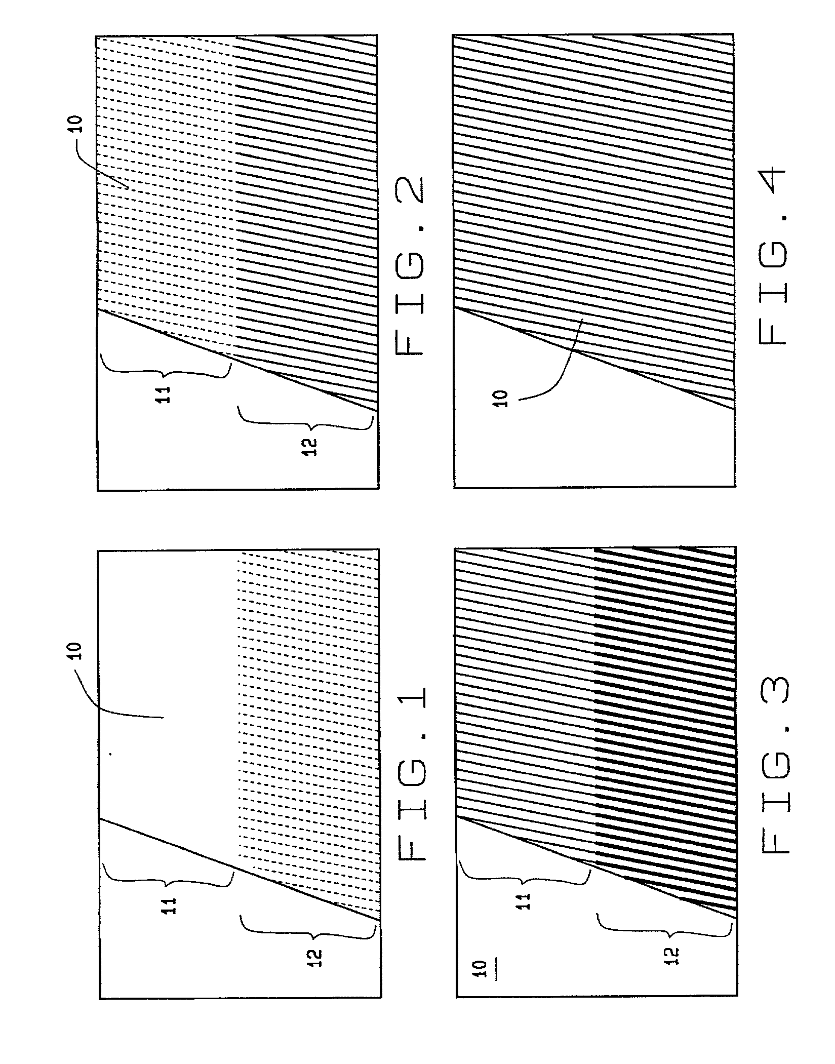
[0016] In a first embodiment of the present invention, an image composed of a set of pixels is obtained from a camera or imaging sensor viewing a scene; for example, an object undergoing non-contact measurement. Each pixel is represented by a set of coordinates (X,Y), identifying the location of the pixel in the image, and a value (Z) representing the level of light intensity at that location. Each pixel thus provides a record of the level of light intensity or illumination at that particular location in the image. The light intensity is initially recorded as an integer value and proportionally ranges fr...


PUM


Abstract

A method for increasing the dynamic light intensity range of an image by combining pixel data from multiple images collected at different levels of illumination intensity to create a single floating-point image representation of an observed scene.

Description

BACKGROUND OF INVENTION[0001] The present invention relates to a method for image processing in a non-contact gauge measurement system, and more particularly, to a method for increasing the dynamic light intensity range of an image by combining or fusing data from multiple images collected at different levels of illumination to create a single floating-point representation of an object undergoing measurement.[0002] Photogrametric measurement systems such as laser range finders, illuminate an object undergoing measurement using structured light. Reflections of the structured light projected on the surface of the object are captured by one or more calibrated cameras, generating images comprised of pixels. These are representative of the light intensity on illuminated portions of the object's surface. In some applications, the structured light is in the form of a set of laser planes. Where the laser planes intersect the surface of the object, a striping effect is achieved. By detecting...

Claims


Application Information

Patent Timeline
Patent Type & Authority Applications(United States)
IPC IPC(8): G01B11/25G01S17/89G06T5/50H04N5/235
CPCG01B11/25G01B11/2536G01S17/89G06T5/50H04N5/235H04N5/2354H04N5/2355H04N23/70H04N23/741H04N23/74
Inventor BROOKSBY, GLEN WILLIAMMUNDY, JOSEPH LEAGRAND
Owner GENERAL ELECTRIC CO
Why Eureka
Try Eureka