
Method and system for controlling distortion of turbine case due to thermal variations

a turbine case and thermal variation technology, applied in the direction of machines/engines, liquid fuel engines, instruments, etc., can solve the problems of complex achievement of gas turbine efficiency, degraded turbine efficiency at a cost of millions of dollars, and increased complexity of turbine cas

Inactive Publication Date: 2003-06-26
GENERAL ELECTRIC CO
View PDF7 Cites 22 Cited by
  • Summary
  • Abstract
  • Description
  • Claims
  • Application Information

AI Technical Summary

Problems solved by technology

If the gap is too small, the airfoils rub against the case causing extensive damage.
However, if the gap is too large, turbine efficiency is degraded at a cost of millions of dollars, for an excess of a few millimeters, over the lifetime of the turbine.
Achievement of gas turbine efficiency is further complicated by the fact that tip clearances vary during operation of the turbine.
For example, the operational thermal environment of a gas turbine is complex, including effects from surrounding hot and cold pipes and the combustion chambers.
The temperature gradients cause thermal stresses that distort the case.
The deviation from a circular cross section reduces the tip clearances, causing the airfoils to rub against the case.
However, as noted above, large tip clearances decrease the efficiency of the turbine at a cost of millions of dollars, for an excess of a few millimeters, over the lifetime of the turbine.
However, given the complex thermal environment of the turbine, design changes can be laborious and time consuming, requiring many iterations.
For example, changing the design of certain hot pipes near the case may provide a more uniform temperature distribution in the steady state, but adversely affect the temperature distribution during transient conditions, such as during start-up, emergency trip, restart, or shut-down operations.
Thus, in addition to being laborious and time consuming, this previous redesign technique can be ineffective.

Method used


Image

  • Method and system for controlling distortion of turbine case due to thermal variations
  • Method and system for controlling distortion of turbine case due to thermal variations
  • Method and system for controlling distortion of turbine case due to thermal variations

Examples


Embodiment Construction

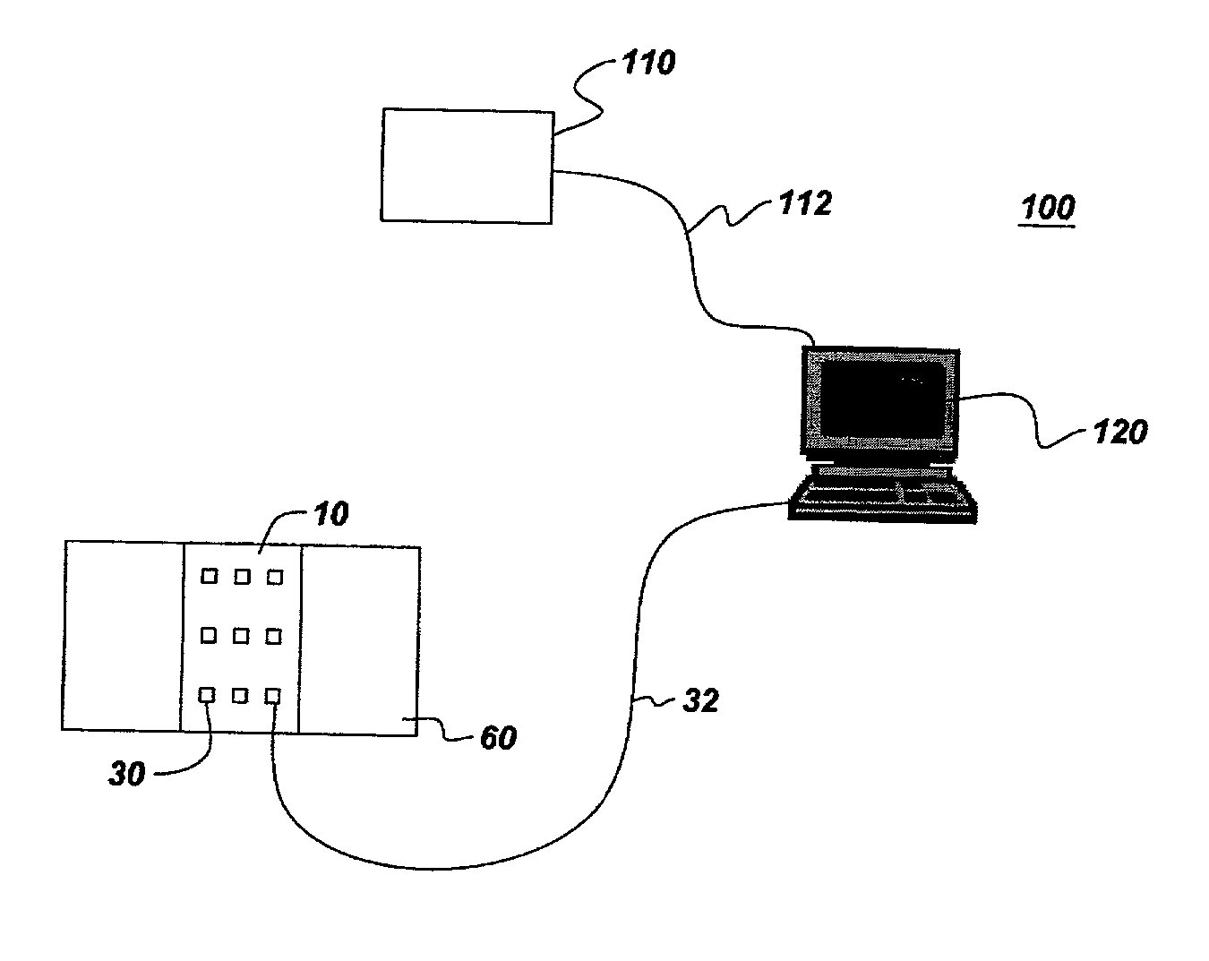
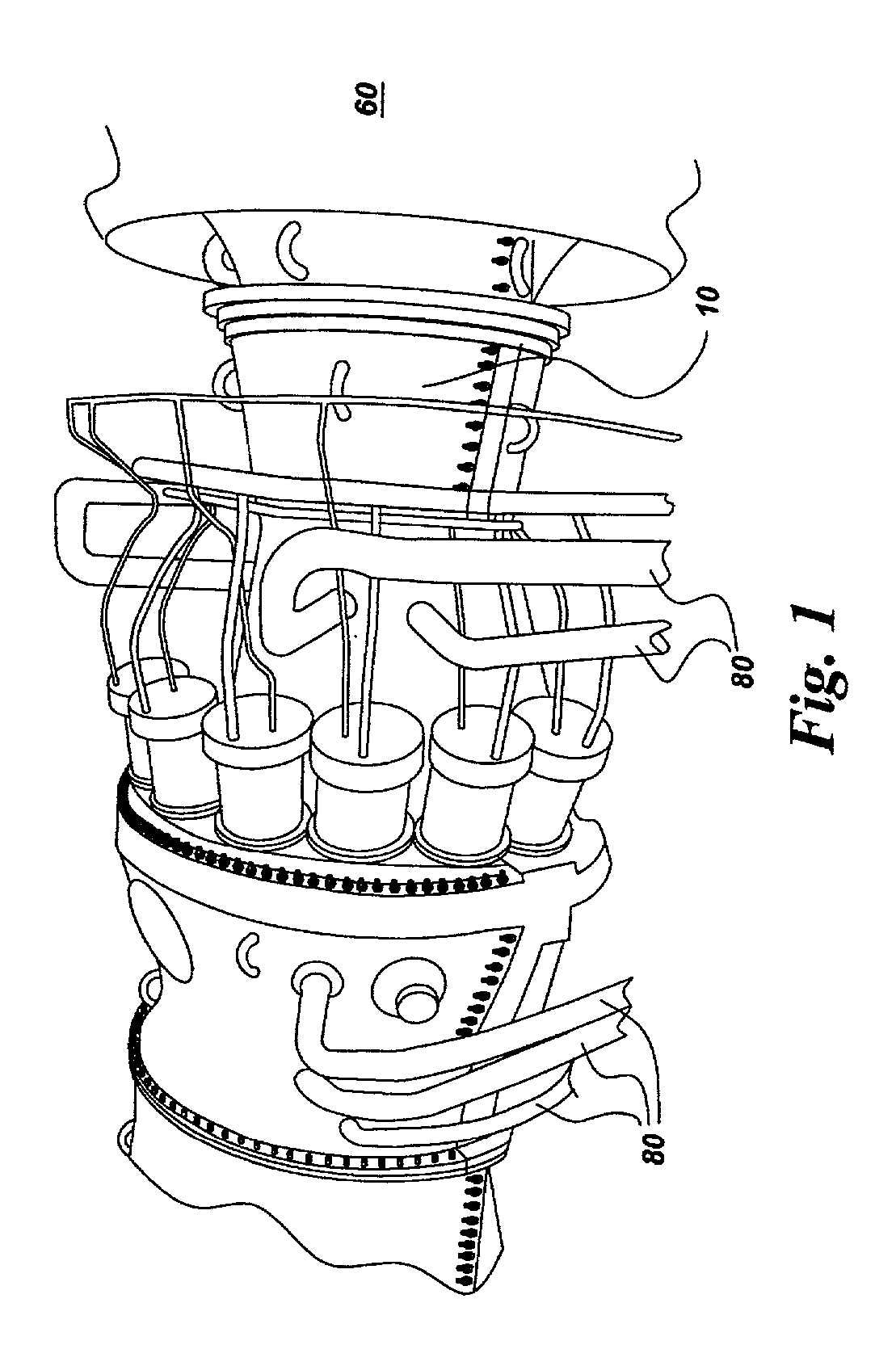
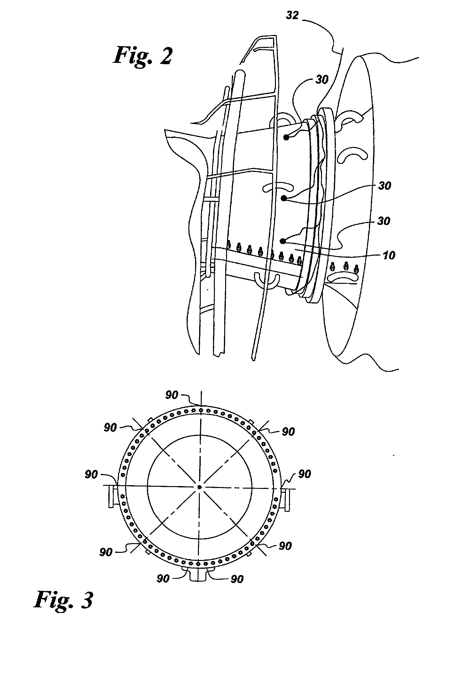
[0020] A method embodiment of the invention for controlling distortion of a turbine case 10 (also referred to as "case") due to thermal variations includes measuring a temperature distribution for the case. The temperature distribution comprises a number of thermal gradients. One exemplary turbine case is a gas turbine case 10, as shown in FIGS. 1 and 2. The temperature distribution is measured using standard measurement techniques, such as thermocouple measurements or infrared radiometry, which are discussed in greater detail below.

[0021] After the temperature distribution is measured, a number of thermal stresses on case 10 are modeled. The thermal stresses are induced by the thermal gradients and are modeled using standard analytical techniques, such as finite element analysis, boundary element methods, closed form solutions, or solid mechanics.

[0022] Next, an out of roundness index O is calculated. The out of roundness index O characterizes the distortion of the case 10 resultin...


PUM


Abstract

A method for controlling distortion of a turbine case ("case") includes measuring a temperature distribution for the case that includes thermal gradients. The method further includes modeling thermal stresses on the case induced by the thermal gradients, calculating an out of roundness index ("index") resulting from the thermal stresses, and comparing the index with at least one distortion limit to determine whether the case has a satisfactory or an unsatisfactory index. The temperature distribution is controlled for an unsatisfactory index to produce the satisfactory index. A system for controlling distortion of the turbine case includes a thermal measurement system, for measuring the temperature distribution, and a computer configured for modeling the thermal stresses, calculating and comparing the index with the distortion limit, and controlling the temperature distribution for an unsatisfactory index to produce the satisfactory index.

Description

BACKGROUND OF INVENTION[0001] The invention relates generally to a method for reducing distortion of a turbine case due to thermal variations and, more particularly, for reducing distortion of a gas turbine case due to thermal variations.[0002] Gas turbines include a rotor and rotating disks that are attached to the rotor. Airfoils (or blades) are positioned at the outer diameter of the disks. These components are surrounded by a case. A gap is present between the tips of the rotor airfoils and the case. If the gap is too small, the airfoils rub against the case causing extensive damage. However, if the gap is too large, turbine efficiency is degraded at a cost of millions of dollars, for an excess of a few millimeters, over the lifetime of the turbine.[0003] Achievement of gas turbine efficiency is further complicated by the fact that tip clearances vary during operation of the turbine. Gas turbine operating conditions vary substantially, based on a combination of intentional and u...

Claims


Application Information

Patent Timeline
IPC IPC(8): F01D17/08F01D21/04F01D21/08F01D25/24F01D25/26
CPCF01D17/085F01D21/04F01D21/08F05D2270/303F01D25/26F05D2270/44F01D25/24
Inventor SEELEY, CHARLES ERKLINRAMAKRISHNAN, RAMANATH IYERCLAEYS, JAMES PATRICKMCCALLUM, MARTEL ALEXANDERTHERMOS, ANTHONY CONSTANTINEWANG, HSIN-PANGWANG, WEIPING
Owner GENERAL ELECTRIC CO
Learn More