These methods suffer from the requirement of a large number of measurement samples to determine the dimensions of the objects, thus taking a long time.
These methods suffer from the erroneous results due to difficulty in interpretation of line pattern when there are surface discontinuities in objects.
Also, these methods produce
ambiguity in matching the reflected line pattern with the illuminated pattern due to widely different
view angle of projection and detection.
Even though conceptually straightforward and inexpensive, it suffers from the heavy computational need for identification of shape characteristics and matching between images.
When the objects lack distinguishable characteristics, such as corners, patterns, edges, etc, these methods result in ambiguous and inaccurate estimates.
Even though these methods can offer relatively accurate measurement, they are difficult to use and involves a number of exposures to attain the accuracy.
(a) It offers the precision of
laser beam methods at a greatly reduced
operating cost and with orders of magnitude greater speed by using projection of a priori known two-dimensional patterns on the objects in the images.
(b) Unlike the
Laser Beam
Triangulation Methods or
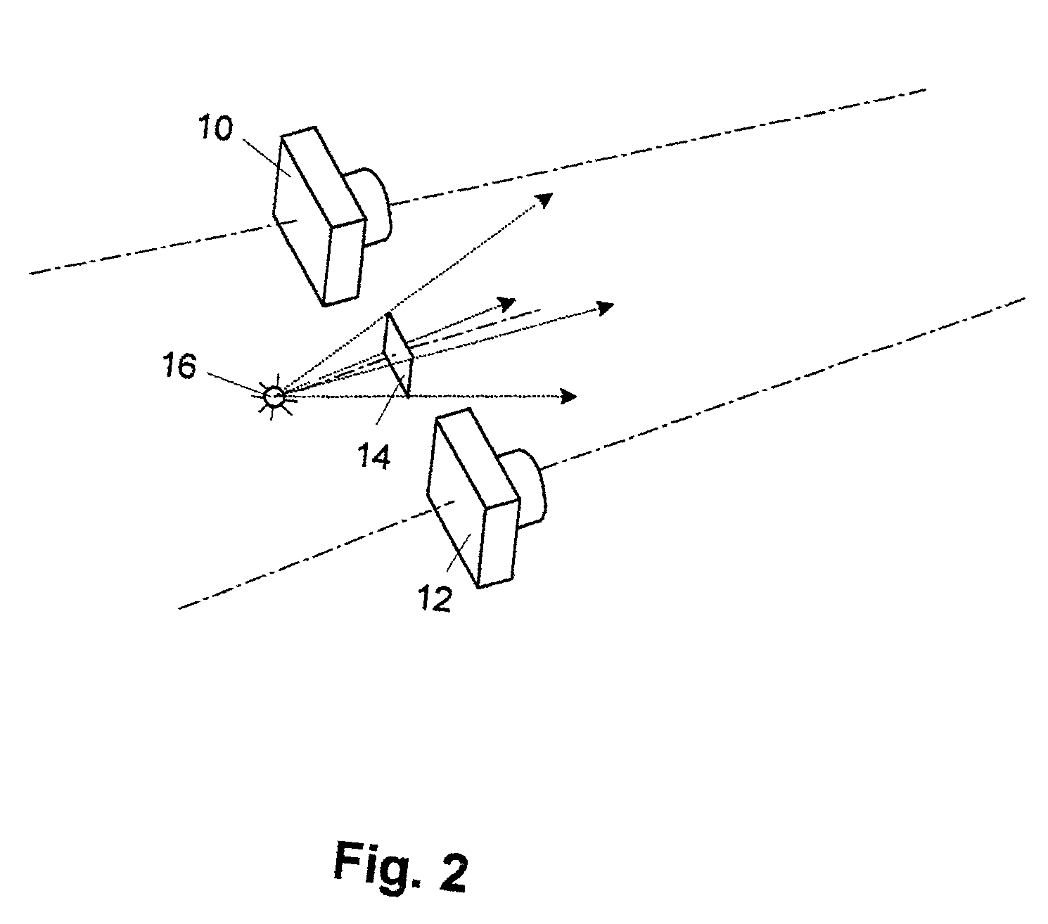
Structured Illumination Methods, it does not require the precision and exactness in the relative location and angles of the projection and the camera. Also, it does not require the projection and the detection should have widely different viewing angle. The projection unit can be located in the vicinity of the cameras. The accuracy of the position and the viewing angle of the projection unit is not critical as long as it projects toward the objects in general.
(c) Relying on the identification of characteristics and features inherent in the objects in the images, as in the conventional Two Cameras Methods, involves a great deal of
ambiguity, thus causing inaccuracy, and heavy computations, thus causing loss of speed. Since the
system of the present invention uses the a priori known two-dimensional patterns which the
computer program is instructed to look for and identify each area in the patterns, identification of a certain pixel or a certain set of pixels in the pattern across images is accurate and fast. This provides a considerable
advantage over the conventional Two Cameras Methods.
(d) Since there is no strict hardware and precision requirements, it offers a great deal of flexibility in the selection of
image detection devices and projection units. Also, the two-dimensional patterns can be customized to suit the needs of any specific application. Under an adverse lighting environment, the contrast of projected patterns can be enhanced by various approaches. For an example, the intensity of the projection can be adjusted to enhance the contrast of patterns. Also, the contrast of patterns detected from a view point can be enhanced by taking a differential of two images acquired under different conditions, such as; 1) the differential between images acquired from the same view point, but one with projection through the pattern
mask and the other without the projection, 2) the differential between images acquired from the same view point with projections, but one with using the pattern
mask and the other without pattern mask, etc.
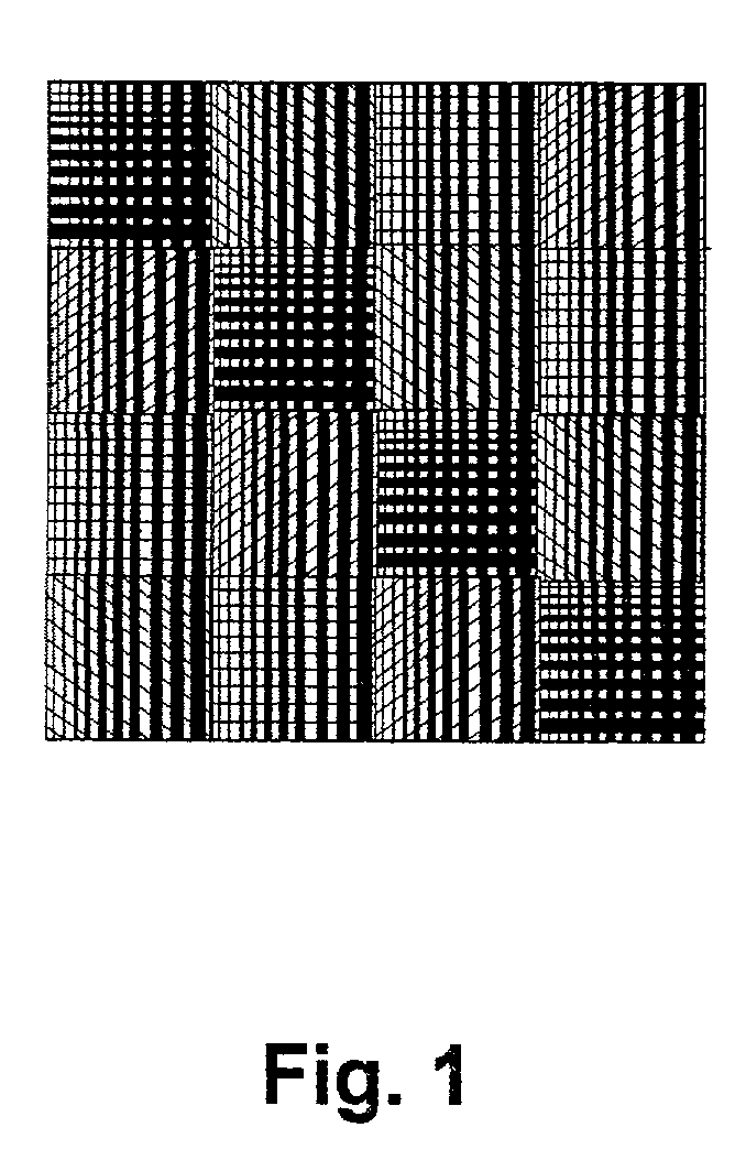
(e) There can be practically
infinite number of different designs of the two-dimensional patterns which can be used for the projection. The only sensible requirement of the pattern is the ease of uniquely identifying each area in the pattern by the
computer program. Typically, a specific subsection in the pattern will be uniquely identified by the shape and / or color characteristics in that subsection area, or sometimes with the aid of those of neighboring subsections. This flexibility allows a customization of patterns using different shapes characteristics and features. Simple black and white patterns can be used, or patterns incorporating color characteristics can be used as needed, or even any selected band of light
wavelength can be used as long as an
image detector can acquire the image with the patterned projection. As long as the pattern is instructed to the
computer program so that it knows what to look for in the acquired images, any customized pattern can be applied.

