Dental magnetic attachment

a magnetic attachment and dentition technology, applied in the field of dentition attachment, can solve the problems of sudden deterioration of fixation and cleanliness, looseness may be caused, and the excellent parts processing in the prior art has had difficulty in achieving the accuracy of dimensions

Inactive Publication Date: 2003-07-03
AICHI STEEL
View PDF0 Cites 21 Cited by
  • Summary
  • Abstract
  • Description
  • Claims
  • Application Information

AI Technical Summary

Problems solved by technology

However maintenance of fixing solely by screwing the screw part 921 to screw hole 911 is not enough, and looseness may be caused during use of said dental attachment.
This looseness may cause sudden deterioration of fixation and cleanliness.
Even excellent parts processing in the prior art has had difficulty to achieve the accuracy of dimensions to adequately screw said taper shaft to said taper hole part and at the same time make said acute angle pointed end of said projecting ring part touch said inclining end face.

Method used


Image

  • Dental magnetic attachment
  • Dental magnetic attachment
  • Dental magnetic attachment

Examples


example 1

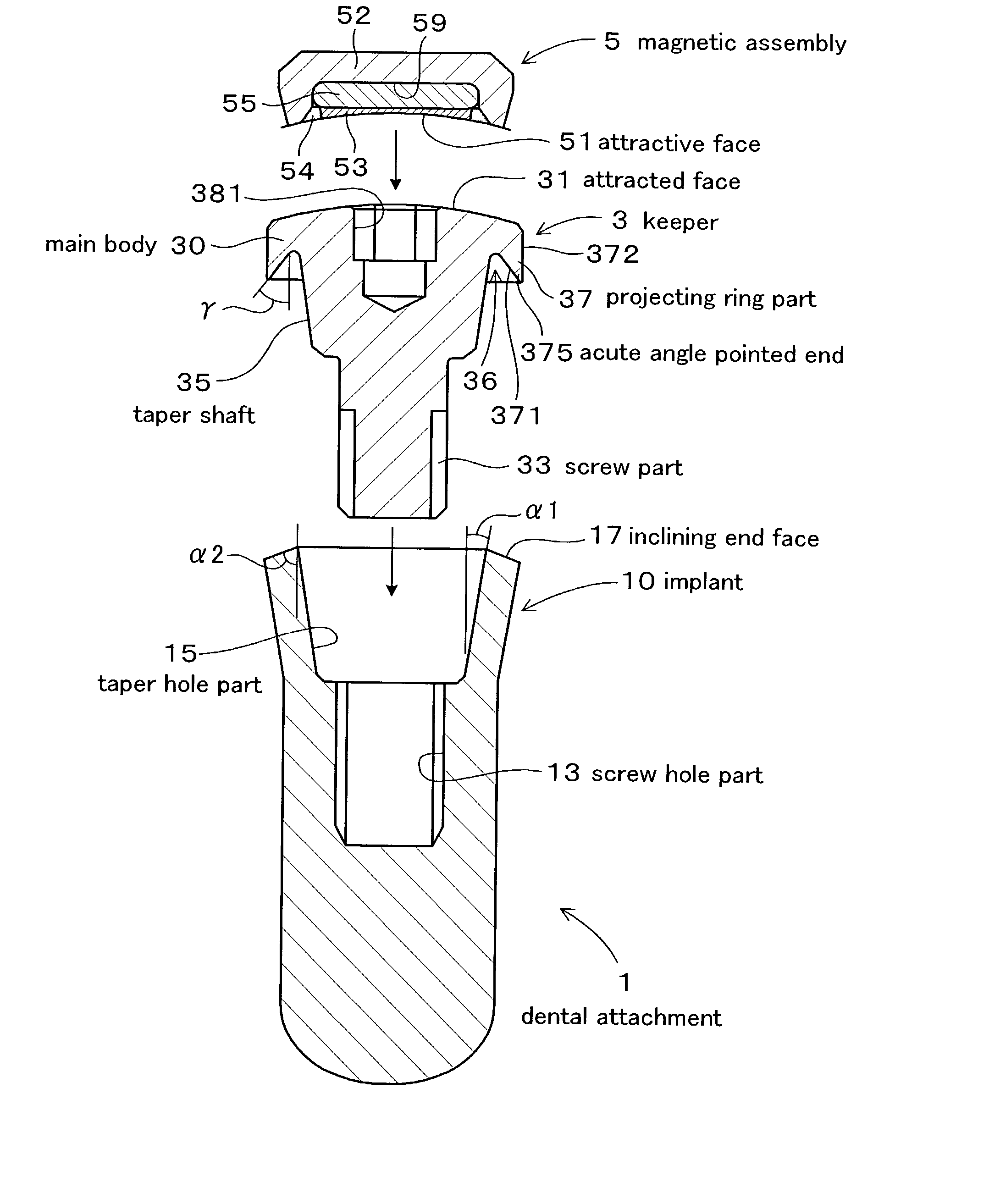
[0055] The dental attachment 1 of this invention, as is shown in FIG. 1, comprises an implant 10 embedded in a jawbone, a keeper 3 supported by said implant 10, and a magnetic assembly 5 which has a contact face 51 to attract a attracted face 31 of said keeper 3 by magnetic attractive force.

[0056] Said keeper 3 has a main body 30 that has attracted surface 31, screw part 33 that is located at the center of the back face opposite the attracted surface 31 of said main body 30, conic taper shaft 35 at the base end of said screw part 33, and projecting ring part 37 which projects toward the shaft to make a ring-shaped groove 36 with said taper shaft 35 at the circumference of said back part.

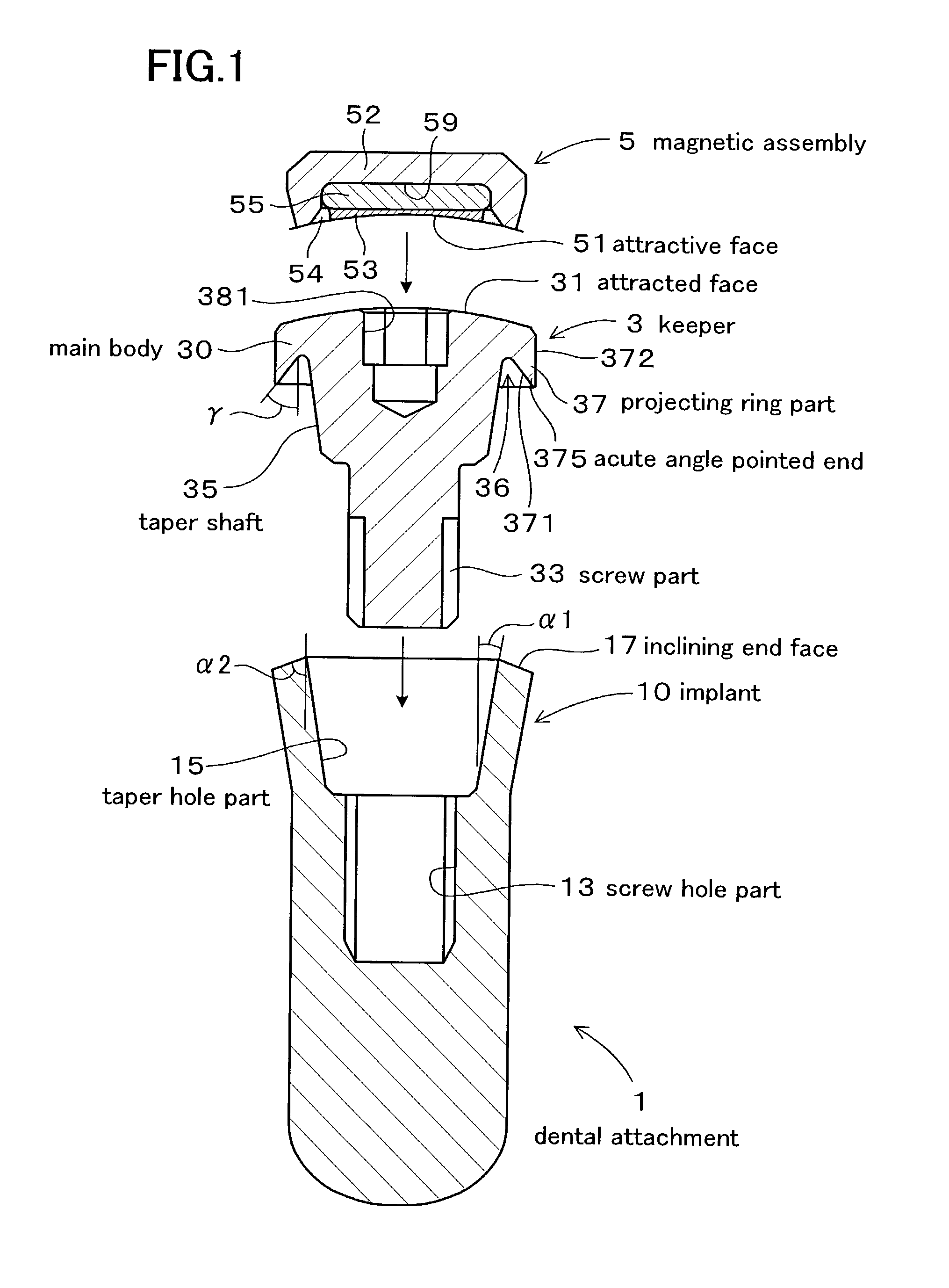
[0057] Said projecting ring 37 has a slanted inner face 371 that tapers toward a pointed end and an acute angle pointed end 375 that actually looks like an acute angle-shape at the pointed part that intersects the circumferential face 372.

[0058] Said implant 10 has a screw hole part 13 into which sai...

example 2

[0080] This example, as shown in FIG. 5, is comprised of an implant which has a little different constitution, a keeper 3, and a magnetic assembly 5.

[0081] Said implant 10, as shown in FIG. 5, is changed into a two-piece structure. Lower part 101 which has a screw hole part 13 and an upper part 102 which has taper hole part 15 and a inclining end face 17.

[0082] Also, said lower part has a hexagonal projecting part 105 on the top end and upper part 102 has a hexagonal concave part 106. By making the projecting part 105 fit to the concave part 106, the precise position of lower part 101 and upper part 102 is determined and rotation between the two pieces is stopped.

[0083] Said keeper 3 has, as is shown in FIG. 5, an attracted face 31 which is flat and has a ring-shaped control part 39 on the circumference. This control part controls the position of magnetic assembly 5.

[0084] Said magnetic assembly 5 has an attractive face which is flat.

[0085] Other structures are about the same as the...


PUM


Abstract

A dental attachment has been invented whose connection force and fitting between an implant and a keeper are improved. A keeper 3 has a main body 10 with a attracted face 31, a screw part 33 that is located at the back face, a conic taper shaft 35, and a projecting ring part 37. The projecting ring part 37 has an inclining inner face 371 and an acute angle pointed end 375. An implant 10 has a screw hole part 13, a conic taper hole part 15 which has about the same inclining angle of the taper axle part 35, and inclining end face 17. When the keeper 3 and the implant 10 are connected, the taper shaft 35 and the taper hole part 15 are fitted closely and at the same time, the inner face 371 of the acute angle pointed end 375 and the inclining end part 17 touch and at least the acute angle pointed end 375 of the projecting ring part 37 is elastically transformed toward the diameter.

Description

BACHGROUND OF THE INVENTION[0001] 1. Field of the Art[0002] The present invention relates to a dental attachment that can be used to fix a denture to a dental implant keeper by magnetic force.[0003] 2. Prior Art[0004] Various dental attachments using magnetic attractive force have been proposed in dental treatments, because it is a simple method to take off and fix the denture.[0005] For example, the dental attachment 9 shown in Japanese Laid-Open Patent Number 9-224959, as shown FIG. 6, consists of an implant 91 acting as an abutment embedded in the jawbone, a keeper 93 fixed to this implant, and a magnetic assembly 95 which has an attractive surface 950 that attracts the attracted surface 930 of the keeper 93 by magnetic attractive force[0006] Said keeper 93 is fixed to said implant 91 by screwing screw part 931 of keeper 93 into screw hole 911 of implant 91. With this, the contact faces 912 and 932 fit together precisely and prevent alien substances from entering between implant ...

Claims


Application Information

Patent Timeline
Patent Type & Authority Applications(United States)
IPC IPC(8): A61C8/00
CPCA61C8/0018A61C8/0037A61C8/005A61C8/0059A61C8/0069A61C8/0081A61C8/0054
Inventor HONKURA, YOSHINOBUARAI, KAZUOTAKEUCHI, YASUHIRO
Owner AICHI STEEL
Why Eureka
Try Eureka