Pressure balancing valve

a technology of pressure balancing valve and spool, which is applied in the field of valves, can solve the problems of reducing the flow passage of the spool section, unable to permit the use of materials of lower strength, and limiting the pressure passage of the prior art valve with its spool, etc., and achieves the effect of eliminating the pressure bleed passag

Inactive Publication Date: 2003-07-17
KOLZE
View PDF5 Cites 1 Cited by
  • Summary
  • Abstract
  • Description
  • Claims
  • Application Information

AI Technical Summary

Benefits of technology

0006] In my invention, elimination of pressure bleed passages has been accomplished by location of the spool pressure force balance means centrally on the spool rather than at the outer spool ends and thereby allows exposure of the spool ends directly to the equal discharge flow pressure instead of through the bleed passaged used in prior art. Also, the central placement of the spool pressure force bal

Problems solved by technology

Prior art valves with their spool pressure passages are somewhat limited in these respects as the pressure passages occupy the space which could be used for assembly fasteners or for improved component strength.
An option of the prior art valves could be to increase the outside diameter of the spool stem to lower the stress, but this would undesirably reduce this section flow passage.
A plastic material would be a preferred lower cost material for these parts, but the stress

Method used


Image

  • Pressure balancing valve
  • Pressure balancing valve

Examples


Embodiment Construction

[0014] Referring now to the drawings, the invention will be described in more detail.

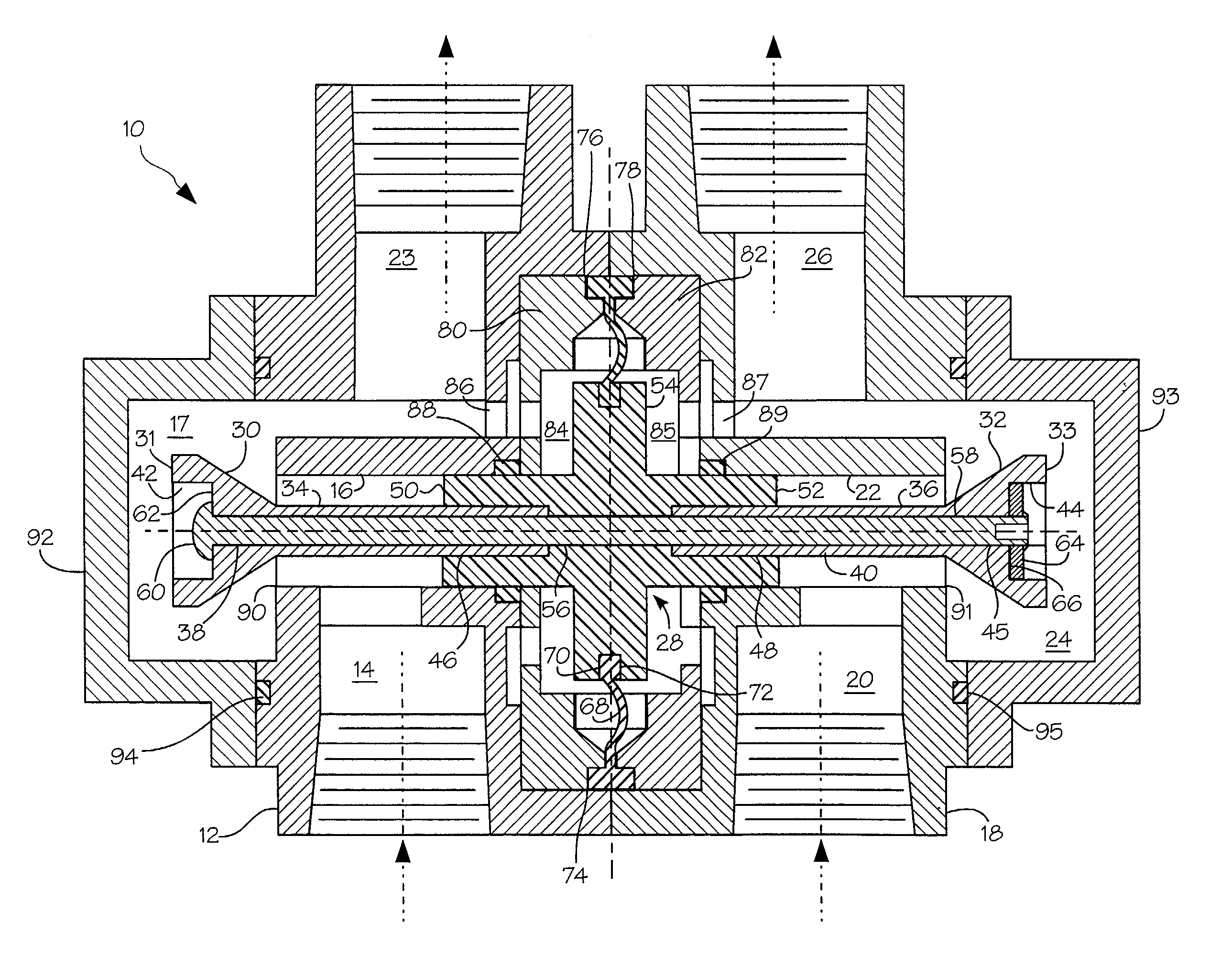
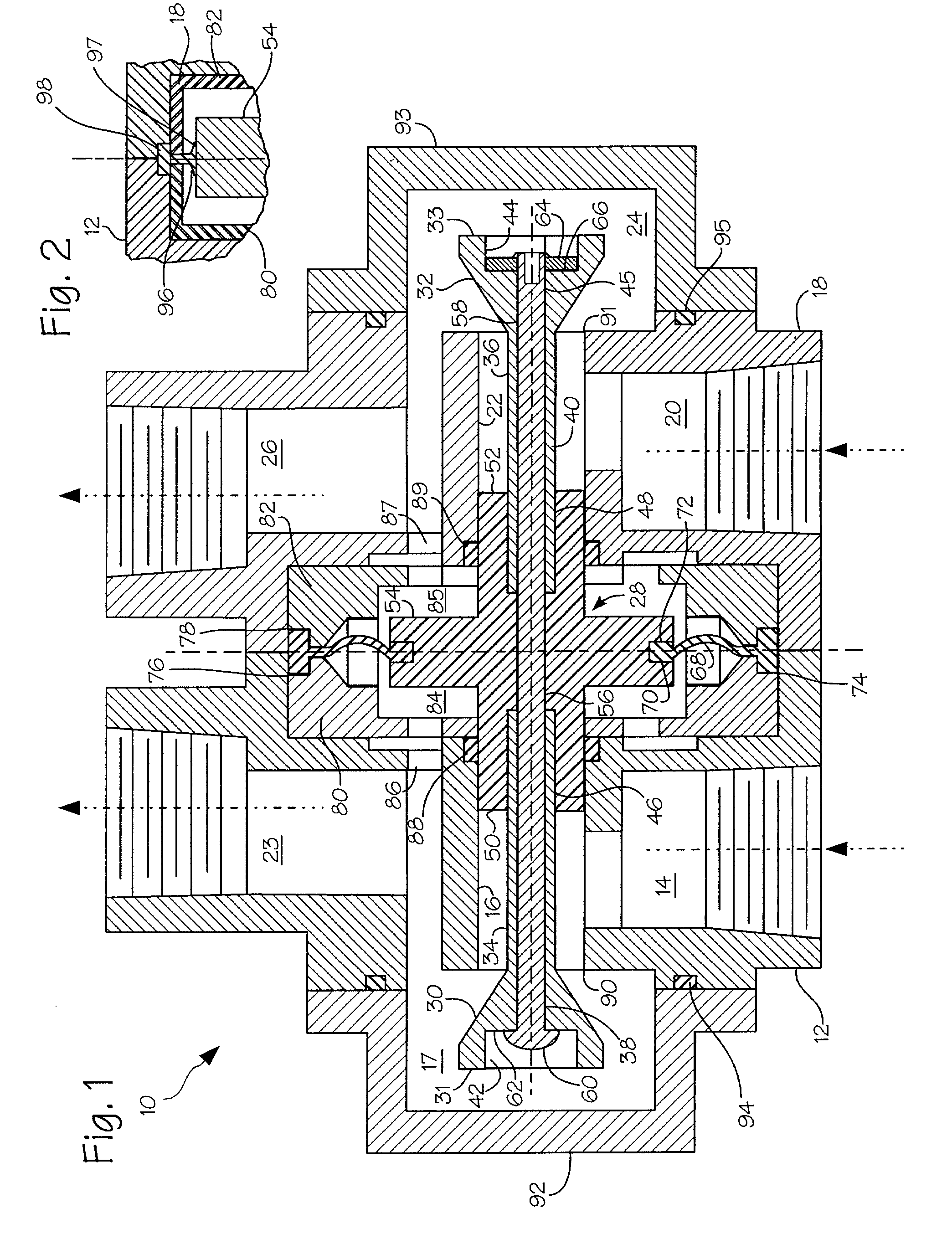
[0015] Referring to FIG. 1, the preferred embodiment of the invention assembly is generally indicated at 10 with a first housing 12 having a first fluid inlet 14, a fluid passage bore 16, and a chamber 17, all communicating with a discharge passage 23; a second housing 18 having a second fluid inlet 20, a fluid passage bore 22, and a chamber 24 all communicating with a discharge passage 26. A spool assembly indicated at 28 and within Assembly 10 comprises poppets 30 and 32 which are formed with respective connecting members 34 and 36 having bores 38 and 40 therethrough and axially connect with counter bores 42 and 44 formed in the non-seating sides of poppets 30 and 32. Poppets 30 and 32 with their respective connecting members 34 and 36 are received within respective counter bores 46 and 48 of respective bosses 50 and 52 which are axially positioned on opposite sides of disk member 54 having a bore...


PUM


Abstract

An improved structural arrangement of a pressure balancing valve of the type where flow between two unequal pressure flowing fluids introduced at the valve inlets is regulated to produce substantially equal pressure flowing fluids at its outlets. The valve assembly incorporates a reciprocating spool member having fluid regulating members at its opposite ends, a pressure sensing member such as a diaphragm or piston member centrally connected to the spool to sense outlet differential pressures of the two fluids and thereby actuate the spool in reciprocating directions whereby said fluid flows are varied by the regulating members to substantially balance the pressure between the two flowing fluids. The structural arrangement permits the balance of pressure forces acting axially across the spool without the need of pressure bleed passages and their possible fluid blockage and also offers advantages of improved corrosion resistance, potential valve size and cost reduction, and high reliability.

Description

BACKGROUND OF INVENTION[0001] This invention relates to valves given the term balancing valves whose functional purpose is to provide a pressure balance between two flowing fluids. These valves have been commercially available for many years and are of many structural embodiments, but all basically operate on the concept first illustrated in a spool valve configuration of U.S. Pat. No. 962,111 by Carl Assmann in 1910 for a Regulating Apparatus for Mixing Valves.[0002] Patent '111 shows all the basic elements commonly used in these valves, i.e., a sensing means to detect the regulated discharge pressure of the two input fluids, a regulating means responding to the sensor means to equalize the discharge pressure of the two fluids, and a pressure balance force means across the regulating means wherein the pressure balance force means are associated with pressure balance passages.[0003] U.S. Pat. No. 4,241,749 by S. G. Petursson for Pressure Compensating Valves reveals several prior art...

Claims


Application Information

Patent Timeline
IPC IPC(8): G05D11/00G05D11/03
CPCG05D11/03G05D11/003G05D16/0647G05D16/028Y10T137/2514
Inventor KOLZE, LAWRENCE A.
Owner KOLZE
Why Eureka
Try Eureka