Surge pressure reduction apparatus with volume compensation sub

a technology of volume compensation and pressure reduction apparatus, which is applied in the direction of fluid removal, sealing/packing, borehole/well accessories, etc., can solve the problems of ineffectiveness, inability to effectively circulate, and inability to shift the sliding sleeve downward into the closed port position

Inactive Publication Date: 2003-07-24
FRANKS INT +1
View PDF0 Cites 48 Cited by
  • Summary
  • Abstract
  • Description
  • Claims
  • Application Information

AI Technical Summary

Benefits of technology

[0016] Furthermore, in the closed port position, apparatus in accordance with the present invention provides a flow path for drilling fluid to flow downward from the drill pipe to the diverter device, from the diverter device to the volume compensation device, from the volume compensation device to the running tool, from the running tool to the tubular member, and from the tubular member out into the borehole. Providing this flow path facilitates circulation and cementing operations.
[0017] Still furthermore, in the open port position, apparatus in accordance with the present invention provides an alternative flow path for drilling fluid to flow upward from the borehole into the tubular member, from the tubular member to the running tool, from the running tool to the volume compensation device, from the volume compensation device to the diverter device, and from the diverter device out into an annulus between the drill pipe and the borehole via the set of housing flow holes. Providing this flow path facilitates surge pressure reduction when lowering the tubular member downhole through drilling fluid.

Problems solved by technology

However, if the drilling / production liner encounters a tight hole or bridge condition within the borehole, then it is not possible to effectively circulate drilling fluid around the end of the drilling / production liner to help free it because the flow holes of the tool will short-circuit the flow of drilling fluid to the annulus outside the tool.
While the surge pressure reduction tool of the '881 patent and the multi-function surge pressure reduction tool of the '522 application provide a mechanism having surge pressure reduction functionality, it has been observed that circumstances may be encountered during the running downhole of a drilling / production liner where a tool in accordance with the '881 patent or the '522 application may be rendered ineffective to facilitate circulation and cementing operations.
Particularly, if a drilling / production liner, while being lowered down the borehole, becomes plugged with drill cuttings and debris that were created and left in the borehole during drilling operations, then it may not be possible to shift the sliding sleeve downward into the closed port position.
Therefore, with the sliding sleeve unable to shift out of the open port position, cementing operations can not be performed at total depth and circulation operations can not be performed if the drilling / production liner encounters a tight hole condition.
This is due to a pressure build-up in the drilling fluid trapped between the yieldable ball seat sealed by the drop ball and the debris blocking the drilling / production liner.
Therefore, the tool cannot be shifted out of the open port position and communication between the surface and the drilling / production liner via the drill pipe is short-circuited by the open flow ports of the tool.

Method used


Image

  • Surge pressure reduction apparatus with volume compensation sub
  • Surge pressure reduction apparatus with volume compensation sub
  • Surge pressure reduction apparatus with volume compensation sub

Examples


first embodiment

[0037] With reference to FIG. 4, the present invention includes a diverter device 100A having a single sequence of surge pressure reduction functionality. The diverter device 100A comprises a housing assembly 301 having an upper end, a lower end, and an axial bore therethrough. The upper end of the housing assembly 301 is operatively connected to a drill string S. The lower end of the housing assembly 301 is operatively connected to a volume compensation device 101 (FIG. 2). The housing assembly 301 includes a set of flow holes 302 formed therein for establishing communication between the annulus outside the diverter device 100A and the axial bore. The axial bore of the housing assembly 301 includes an upper circumferential groove 304A and a lower circumferential groove 304B formed therein.

[0038] Still with reference to FIG. 4, a sleeve 303 having an upper end and a lower end is arranged within the axial bore of the housing 301. A plurality of latching fingers 305 are formed on the ...

second embodiment

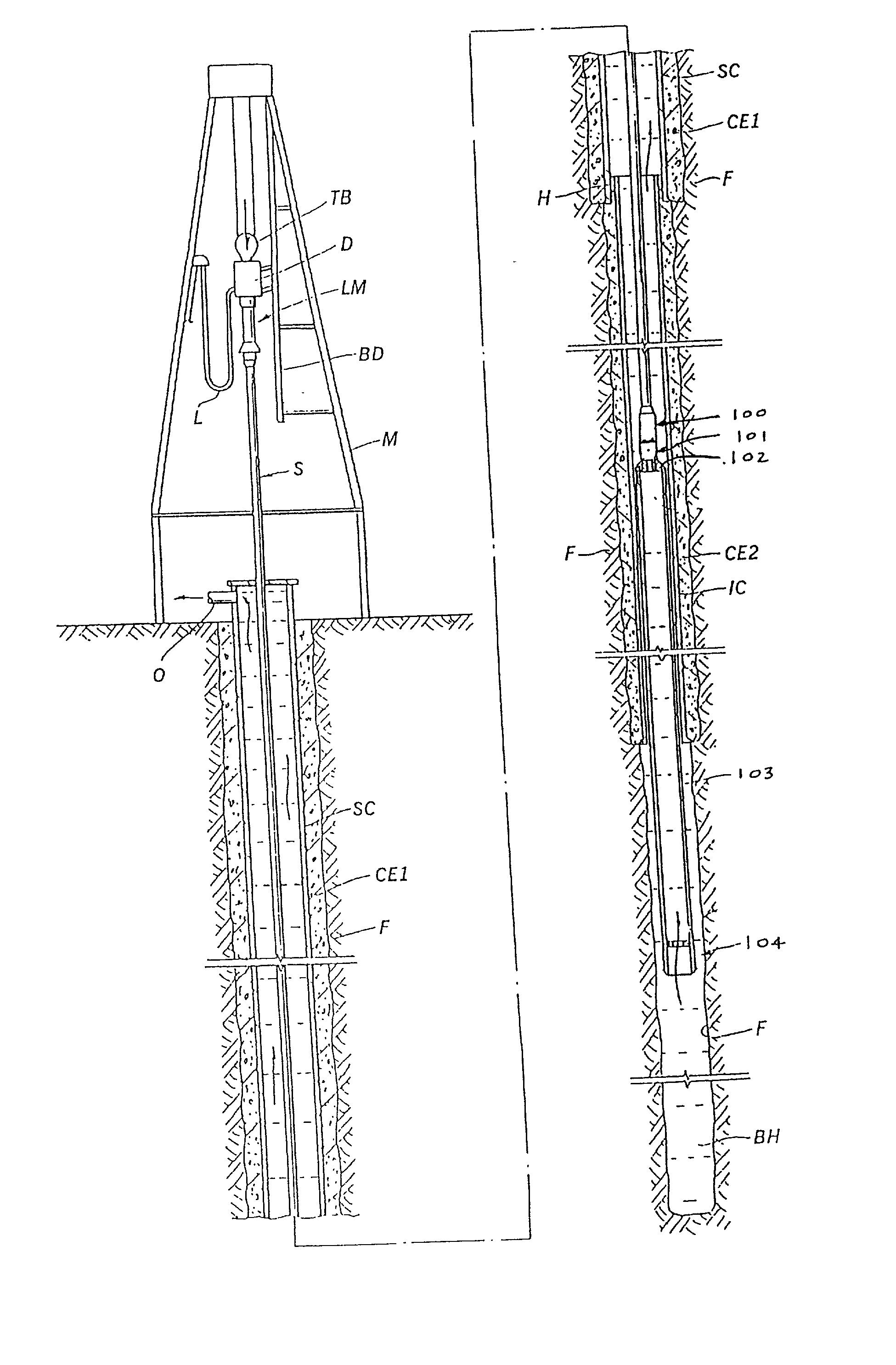
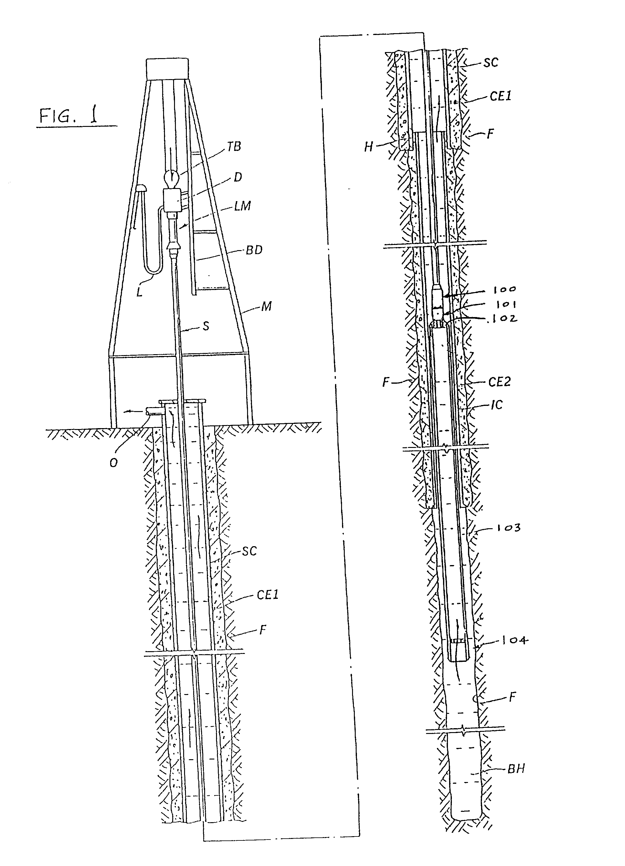
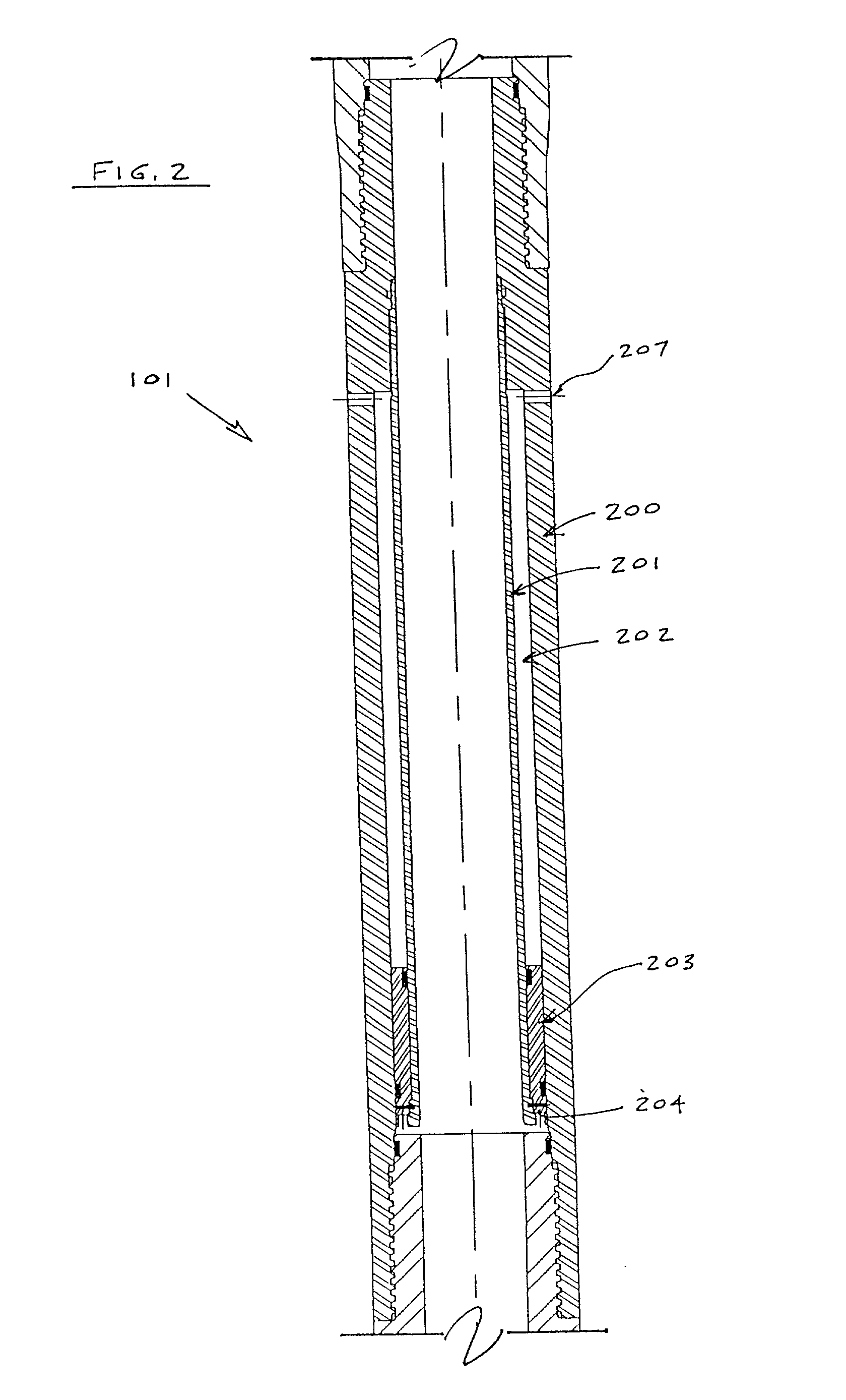
[0044] With reference to FIGS. 7 and 8, the present invention includes a diverter device 100B having multiple sequences of surge pressure reduction functionality. The diverter device 100B comprises a housing assembly with an upper housing 401 and a lower housing 402 which are in threaded engagement with one another. The upper housing 401 is in threaded engagement with a top sub 403, and the lower housing 402 is in threaded engagement with a volume compensation device 101. The volume compensation device 101 is in threaded connection with a bottom sub 404. The top sub is operatively connected to the drill string S (FIG. 1). The bottom sub is operatively connected to the drilling / production liner 103 via running tool 102 (FIG. 1).

[0045] With reference to FIGS. 7-9., the housing assembly 401, 402 contains a yieldable ball seat 410 connected to a camming sleeve 411. The lower end of a dart directing sleeve 412 is connected to the yieldable ball seat 410, and a snap ring 413 is utilized t...


PUM


Abstract

A method and apparatus for use in the oil well industry for running in drilling / production liners and sub-sea casings down a borehole on a drill pipe using a running tool with the benefits of surge pressure reduction are disclosed. A surge pressure reduction tool in accordance with the present invention includes a diverter device having a set of flow holes which diverter device can be shifted between a "surge pressure reduction" mode and a "cementing" or "circulation" mode. A tool in accordance with the present invention further includes a volume compensation device which enables the diverter device to shift axially downward into the cementing or circulation mode even where the drilling / production liner or sub-sea casing is plugged with drill cuttings or downhole debris. In the cementing / circulation mode, a flow path is established for cement / drilling fluid to flow downward from the drill pipe, through the diverter device, volume compensation device, and running tool, and out into the borehole via the drilling / production liner or sub-sea casing. In the surge pressure reduction mode, an alternative flow path is established for drilling fluid to flow upward from the borehole into the drilling / production liner or sub-sea casing, through the running tool and volume compensation device, and into an annulus between the drill pipe and the borehole via the set of flow holes of the diverter device.

Description

[0001] 1. Field of the Invention[0002] The present invention relates to a method and apparatus for providing surge pressure reduction functionality while running a drilling / production liner or sub-sea casing down a borehole.[0003] 2. Description of the Prior Art[0004] The principle of operation of a surge pressure reduction tool is described in U.S. Pat. No. 5,960,881 ("the '881 patent"), which is incorporated herein by reference and which should be referred to with respect to the advantages provided by that invention.[0005] The invention of the '881 patent has provided the oil well industry with the long-desired capability of running in a drilling / production liner or sub-sea casing faster and more reliably with a minimum of lost drilling fluid. Particularly, the surge pressure reduction tool comprises a housing assembly connected between a drill pipe and a drilling / production liner. The housing assembly includes a set of flow holes and an axial bore formed therein. A sliding sleeve...

Claims


Application Information

Patent Timeline
Patent Type & Authority Applications(United States)
IPC IPC(8): E21B21/08E21B21/10
CPCE21B21/08E21B23/004E21B21/103
Inventor ALLAMON, JERRY P.MILLER, JACK E.
Owner FRANKS INT
Why Eureka
Try Eureka