
Controlled alignment of catalytically grown nanostructures in a large-scale synthesis process

a nanostructure and large-scale synthesis technology, applied in the field of nanostructures, can solve the problems of insufficiently meeting the requirements of synthesizing large quantities of elongated nanostructures with well defined properties, arranging them in a desired configuration, and facilitating the creation of input/output connections

Inactive Publication Date: 2003-08-07
UNIV OF TENNESSEE RES FOUND +1
View PDF7 Cites 39 Cited by
  • Summary
  • Abstract
  • Description
  • Claims
  • Application Information

AI Technical Summary

Benefits of technology

[0058] The invention, can be cost effective and advantageous for at least the following reasons. The invention allows the fabrication of nanostructures aligned at a (continuously) variable angle to the substrate, not just vertically aligned nanostructures. The invention allows the fabrication of "kinked" nanostructures that consist of several sections that all can be aligned at different angles to the substrate. The invention improves quality and / or reduces costs compared to previous approaches.[0059] All the disclosed embodiments of the invention disclosed herein can be made and used without undue experimentation in light of the disclosure. The invention is not limited by theoretical statements recited herein. Although the best mode of carrying out the invention contemplated by the inventor(s) is disclosed, practice of the invention is not limited thereto. Accordingly, it will be appreciated by those skilled in the art that the invention may be practiced otherwise than as specifically described herein.[0060] Fabrication of nanostructures other than CNFs or CNTs. The only requirement is that the growth process of these nanostructures should be similar to the catalytic growth of CNFs / CNTs. Different sample holder shape can be used. Different catalyst can be used. Different gasses can be used.[0061] Further, the individual components need not be formed in the disclosed shapes, or combined in the disclosed configurations, but could be provided in virtually any shapes, and / or combined in virtually any configuration. Further, the individual components need not be fabricated from the disclosed materials, but could be fabricated from virtually any suitable materials. Further, variation may be made in the steps or in the sequence of steps composing methods described herein. Further, although the electrode described herein can be a separate module, it will be manifest that the electrode may be integrated into the system with which it is associated. Furthermore, all the disclosed elements and features of each disclosed embodiment can be combined with, or substituted for, the disclosed elements and features of every other disclosed embodiment except where such elements or features are mutually exclusive.[0062] It will be manifest that various substitutions, modifications, additions and / or rearrangements of the features of the invention may be made without deviating from the spirit and / or scope of the underlying inventive concept. It is deemed that the spirit and / or scope of the underlying inventive concept as defined by the appended claims and their equivalents cover all such substitutions, modifications, additions and / or rearrangements.[0063] The appended claims are not to be interpreted as including means-plus-function limitations, unless such a limitation is explicitly recited in a given claim using the phrase(s) "means for" and / or "step for." Subgeneric embodiments of the invention are delineated by the appended independent claims and their equivalents. Specific embodiments of the invention are differentiated by the appended dependent claims and their equivalents.

Problems solved by technology

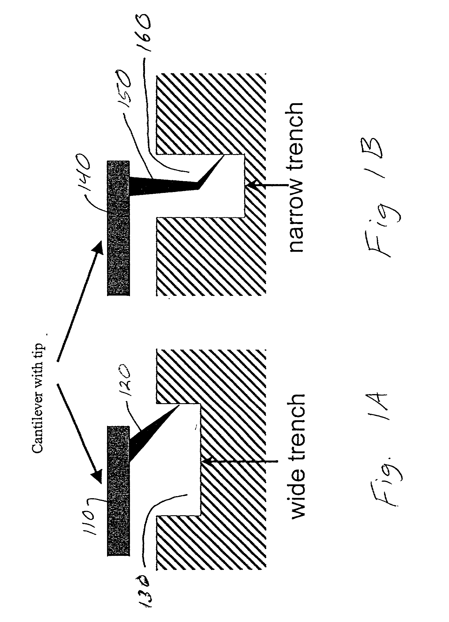
Despite vast advances in this field, there remain unsolved problems such as the requirements to (a) synthesize large quantities of CNTs with predetermined properties, (b) place them in a required configuration and (c) create IO connections, all in the context of a fast mass production fabrication process.
Heretofore, the requirements of synthesizing large quantities of elongated nanostructures with well defined properties, arranging them in a desired configuration, and facilitating the creation of input / output connections have not been fully met.

Method used


Image

  • Controlled alignment of catalytically grown nanostructures in a large-scale synthesis process
  • Controlled alignment of catalytically grown nanostructures in a large-scale synthesis process
  • Controlled alignment of catalytically grown nanostructures in a large-scale synthesis process

Examples


Embodiment Construction

[0022] The invention and the various features and advantageous details thereof are explained more fully with reference to the nonlimiting embodiments that are illustrated in the accompanying drawings and detailed in the following description. Descriptions of well known starting materials, processing techniques, components and equipment are omitted so as not to unnecessarily obscure the invention in detail. It should be understood, however, that the detailed description and the specific examples, while indicating preferred embodiments of the invention, are given by way of illustration only and not by way of limitation. Various substitutions, modifications, additions and / or rearrangements within the spirit and / or scope of the underlying inventive concept will become apparent to those skilled in the art from this disclosure.

[0023] Within this application several publications are referenced by author's name and publication year within parentheses. Full citations for these, and other, pu...


PUM

PropertyMeasurementUnit
Compositionaaaaaaaaaa
Electric fieldaaaaaaaaaa

Abstract

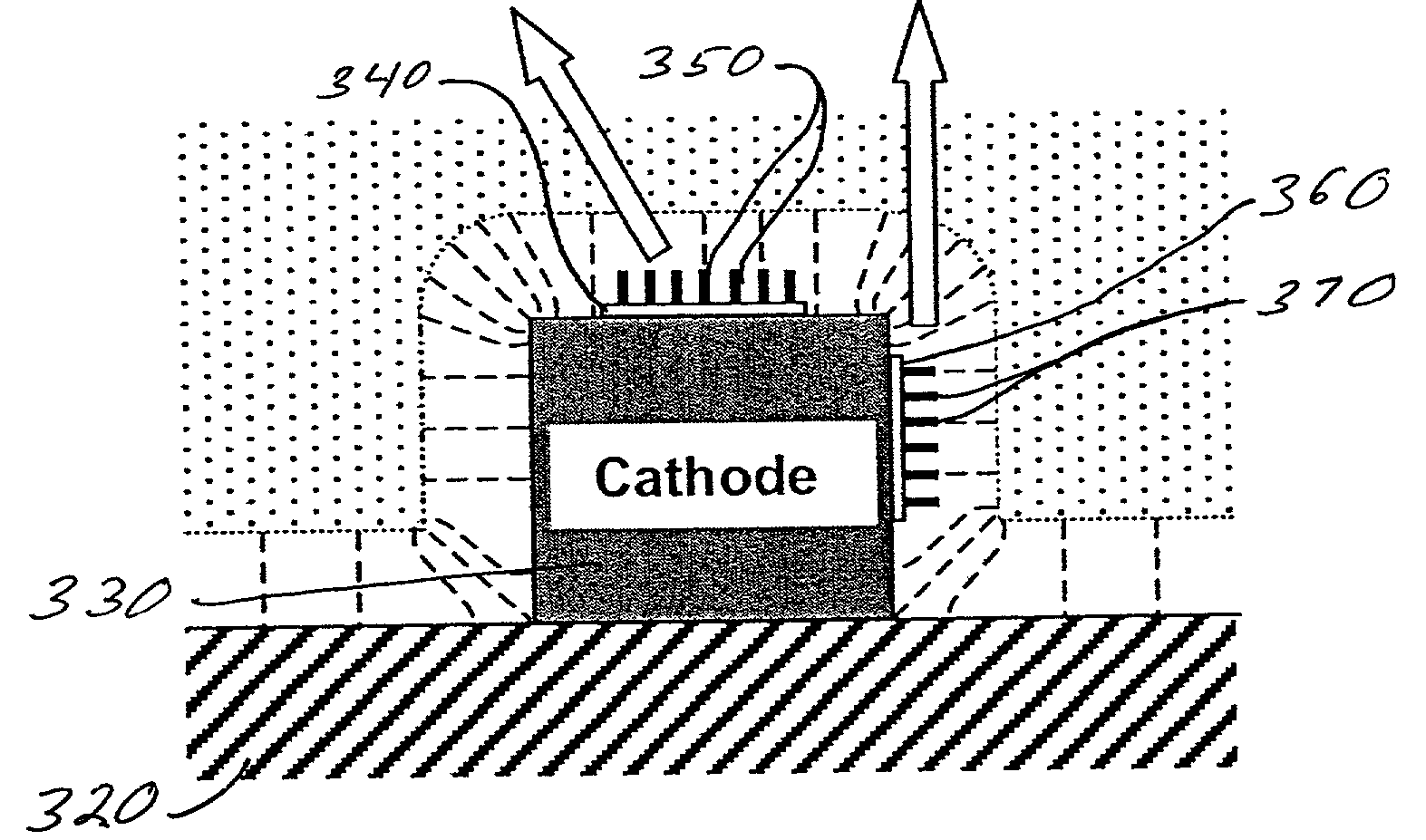
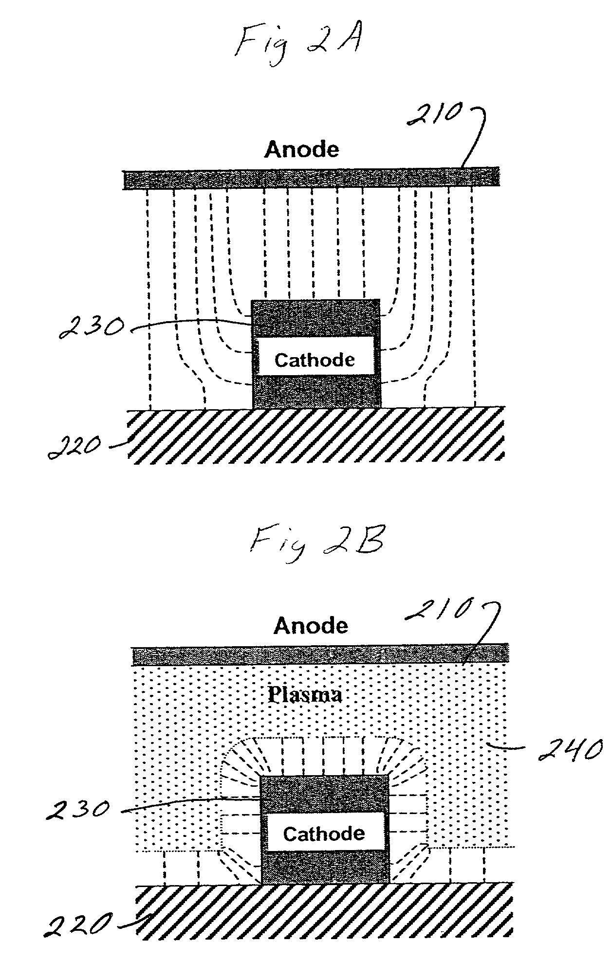
Systems and methods are described for controlled alignment of catalyticaly grown nanostructures in a large-scale synthesis process. A method includes: generating an electric field proximate an edge of a protruding section of an electrode, the electric field defining a vector; and forming an elongated nanostructure located at a position on a surface of a substrate, the position on the surface of the substrate proximate the edge of the protruding section of the electrode, at least one tangent to the elongated nanostructure i) substantially parallel to the vector defined by the electric field and ii) substantially non-parallel to a normal defined by the surface of the substrate.

Description

[0001] This invention was made with United States Government support under contract to UT-Battelle, L.L.C. The Government has certain rights in this invention.[0002] 1. Field of the Invention[0003] The invention relates generally to the field of nanotechnology. More particularly, the invention relates to nanostructures that are elongated, methods of making elongated nanostructures and machinery for making such nanostructures.[0004] 2. Discussion of the Related Art[0005] The fabrication of commercially valuable devices based upon nanoscale components requires large-scale processes that allow massive production of these components. As a practical matter, such large scale processes need to i) mass produce nanoscale components with well specified properties, (e.g., shape, structure, chemical composition, etc.), ii) enable secure placement of these components in an appropriate orientation that may be dictated by end product functionality, and iii) facilitate attachment of robust input an...

Claims


Application Information

Patent Timeline
IPC IPC(8): A61K9/14B82B1/00C01B31/02C23C16/26D01F9/127G01N33/543H01J1/304H01J1/62H01J37/32H01L21/44H01L21/8234H01L21/8244H01L29/06H01L31/0328H01L31/0336H01L31/072H01L31/109
CPCB82Y30/00B82Y40/00C01B31/0233C01B2202/08Y10T428/24628G01N33/5438Y10S977/843Y10S977/891Y10S977/943D01F9/127C01B32/162
Inventor MERKULOV, VLADIMIR I.MELECHKO, ANATOLI V.GUILLORN, MICHAEL A.LOWNDES, DOUGLAS H.SIMPSON, MICHAEL L.
Owner UNIV OF TENNESSEE RES FOUND
Learn More