
Control apparatus for power train including continuously variable transmission

a technology of control apparatus and transmission device, which is applied in the direction of mechanical actuated clutches, couplings, couplings, etc., can solve the problems of belt or power roller slipping, wear of the portion of the pulley or disc that is in contact with the belt or power roller, and the cvt will not be able to perform the intended function of transmitting power at a given speed ratio

Inactive Publication Date: 2003-08-14
TOYOTA JIDOSHA KK
View PDF22 Cites 22 Cited by
  • Summary
  • Abstract
  • Description
  • Claims
  • Application Information

AI Technical Summary

Benefits of technology

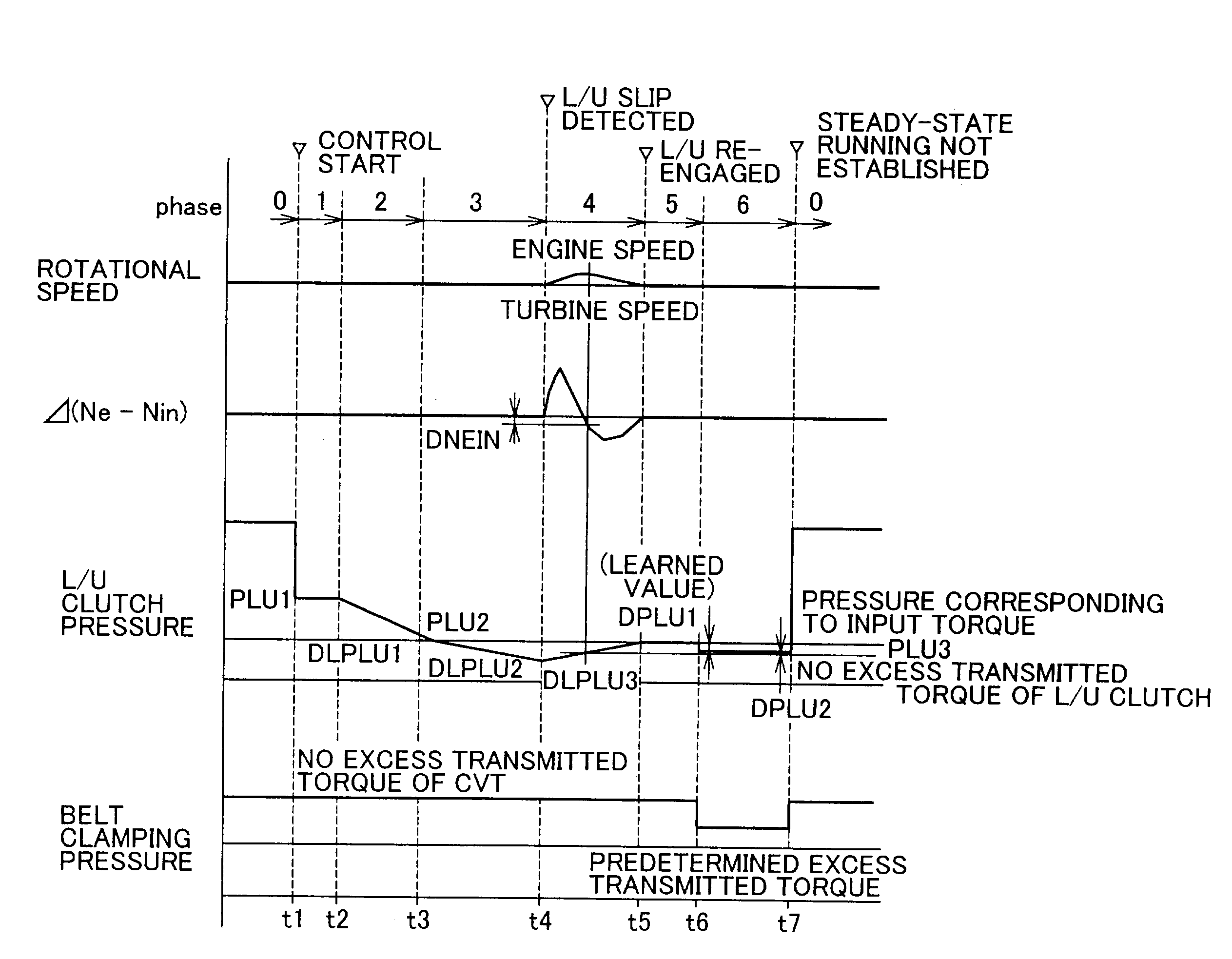
[0016] With the above arrangement, the clutch coupled in series with the CVT is prevented from repeating engagement and slippage. Furthermore, since the engaging pressure is corrected with the learned value that reflects the actual operating state of the power train, an excess amount of transmitted torque for accommodating a slip of the clutch can be controlled to an appropriate value, whereby the clamping pressure of the CVT can be reduced to the minimum within a range in which no slip occurs, thus assuring improved fuel economy.
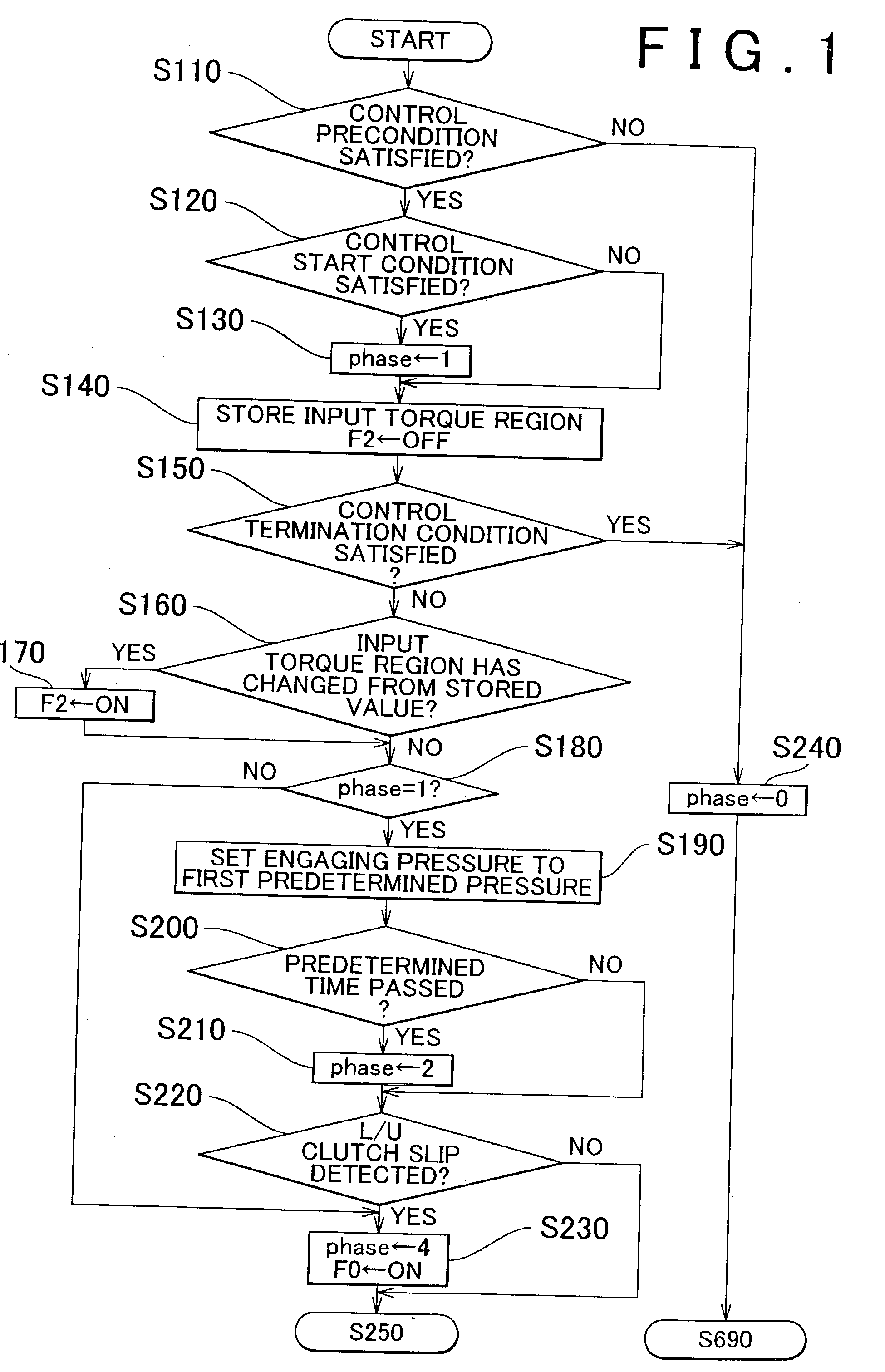
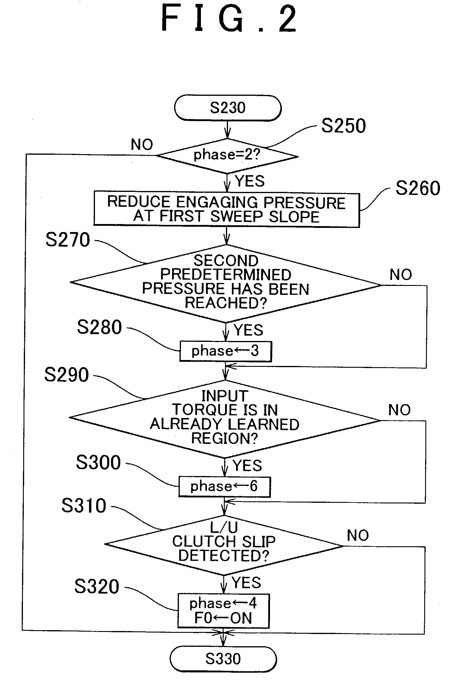
[0058] When a slip of the clutch occurs in the process of controlling the engaging pressure of the clutch to a pressure level that provides a certain excess transmitted torque, the engaging pressure is increased so as to re-engage the clutch, and learning of the engaging pressure is inhibited. Thus, an excessively large slip of the clutch can be avoided, and at the same time erroneous learning of the engaging pressure can be avoided.

Problems solved by technology

If a torque applied to the CVT exceeds the torque capacity, a slip of the belt or power roller occurs.
If an excessive slip of the belt or power roller occurs, a portion of the pulley or disc that is in contact with the belt or power roller wears.
As a result, the worn portion of the pulley or disc will not serve to transmit torque, and the CVT will not be able to perform its intended function of transmitting power at a given speed ratio.
If the clamping pressure is increased, however, the power transmitting efficiency of the CVT is reduced, and a large quantity of power is consumed for driving an oil pump that generates a hydraulic pressure, resulting in deteriorated fuel economy of the vehicle.
However, an unexpected or sudden torque may occur even in a steady or quasi-steady running state, which makes it necessary to prevent or avoid a slip of the CVT even in this case.
In this manner, the engaging pressure and the clamping pressure are repeatedly reduced and increased, resulting in repeated slips of the clutch.
With the known control device as described above, therefore, the power transmitting efficiency of the power train may be reduced, and the fuel economy may be deteriorated or may not be improved owing to the use of the CVT.
Since the known device as disclosed in the above-identified publication does not take these variations into consideration when increasing the engaging pressure and the clamping pressure after detection of a slip of the clutch, the engaging pressure of the clutch may become excessively large relative to the clamping pressure.
In such a case, an excess of the engaging pressure of the clutch may become substantially equal to or larger than that of the clamping pressure of the CVT, which may result in occurrence a slip of the CVT.
This is because a slip may occur to the CVT if the torque capacity of the CVT is reduced when the learned value deviates in the decreasing direction because of some abnormality.
As part of the control to be inhibited, the engaging pressure of the clutch is reduced so as to cause a slip, and is then increased for re-engagement, thus giving rise to a possibility that judder may occur again.

Method used


Image

  • Control apparatus for power train including continuously variable transmission
  • Control apparatus for power train including continuously variable transmission
  • Control apparatus for power train including continuously variable transmission

Examples


Embodiment Construction

[0090] Some exemplary embodiments of the invention will be described in detail. Initially, a power train including a continuously variable transmission, which employs a control apparatus according to the invention, will be explained. The continuously variable transmission of the power train installed on a vehicle may be a belt-and-pulley type continuously variable transmission using a belt as a torque transmitting member, or may be a toroidal-type (or traction-type) continuously variable transmission using a power roller as a torque transmitting member and utilizing shearing force of oil (traction oil) for transmitting torque. FIG. 23 schematically shows one example of a vehicle power train including a belt-and-pulley type continuously variable transmission 1 (which will be referred to as "CVT" when appropriate). As shown in FIG. 23, the CVT 1 is operatively connected to a driving power source 4 via a forward / reverse drive switching mechanism 2 and a torque converter 3.

[0091] The dr...


PUM


Abstract

A control apparatus for a power train including a continuously variable transmission and a clutch arranged in series with the continuously variable transmission is provided in which an engaging pressure of the clutch is first reduced until a slip occurs, and is then increased after detection of the slip so as to re-engage the clutch, and an engaging pressure of the clutch to be established is calculated by giving an excess pressure to the engaging pressure at which the clutch is re-engaged, such that an excess amount of the transmitted torque of the clutch is set smaller than that of the continuously variable transmission. The control apparatus is adapted to determine a learned value as a correction value of the engaging pressure that is set in advance in accordance with an input torque applied to the clutch, based on the engaging pressure calculated by giving the excess pressure to the engaging pressure at which the clutch is re-engaged.

Description

INCORPORATION BY REFERENCE[0001] The disclosure of Japanese Patent Applications No. 2002-027417 filed on Feb. 4, 2002 and No. 2002-198031 filed on Jul. 5, 2002, each including the specification, drawings and abstract, is incorporated herein by reference in its entirety.[0002] 1. Field of the Invention[0003] The invention relates to a control apparatus for a power train including a continuously variable transmission in which a torque transmitting member, such as a belt or a power roller, for transmitting torque is in direct or indirect contact with rotary members, such as pulleys or discs, and which has a variable torque capacity that varies depending upon a contact pressure between the torque transmitting member and the rotary members. In particular, the invention relates to such a control apparatus adapted for controlling an engaging pressure of a clutch that is arranged in series with the continuously variable transmission.[0004] 2. Description of Related Art[0005] Known continuou...

Claims


Application Information

Patent Timeline
Patent Type & Authority Applications(United States)
IPC IPC(8): F16D48/06F16H61/662
CPCB60W2510/0241B60W2710/025F16D48/066Y10T477/624F16H2061/6618Y10T477/6203F16H61/66272F16D2500/10412F16D2500/1088F16D2500/30406F16D2500/30412F16D2500/30814F16D2500/50236F16D2500/70406F16D2500/70426F16D2500/70605
Inventor HOSHIYA, KAZUMINAKAWAKI, YASUNORIIWATSUKI, KUNIHIROOSHIUMI, YASUHIRO
Owner TOYOTA JIDOSHA KK
Learn More