
Fuel system, method for operating the fuel system, computer programme and control device and/or regulator for controlling said system

a fuel system and fuel technology, applied in the field of fuel systems, can solve problems such as fuel supply

Inactive Publication Date: 2003-08-21
ROBERT BOSCH GMBH
View PDF4 Cites 23 Cited by
  • Summary
  • Abstract
  • Description
  • Claims
  • Application Information

AI Technical Summary

Problems solved by technology

Supplying fuel to the combustion chambers of the engine during the starting process is a fundamental problem in fuel systems.
In many cases, this increased delivery pressure is sufficient to start the engine in an extremely short period of time.

Method used


Image

  • Fuel system, method for operating the fuel system, computer programme and control device and/or regulator for controlling said system
  • Fuel system, method for operating the fuel system, computer programme and control device and/or regulator for controlling said system
  • Fuel system, method for operating the fuel system, computer programme and control device and/or regulator for controlling said system

Examples


Embodiment Construction

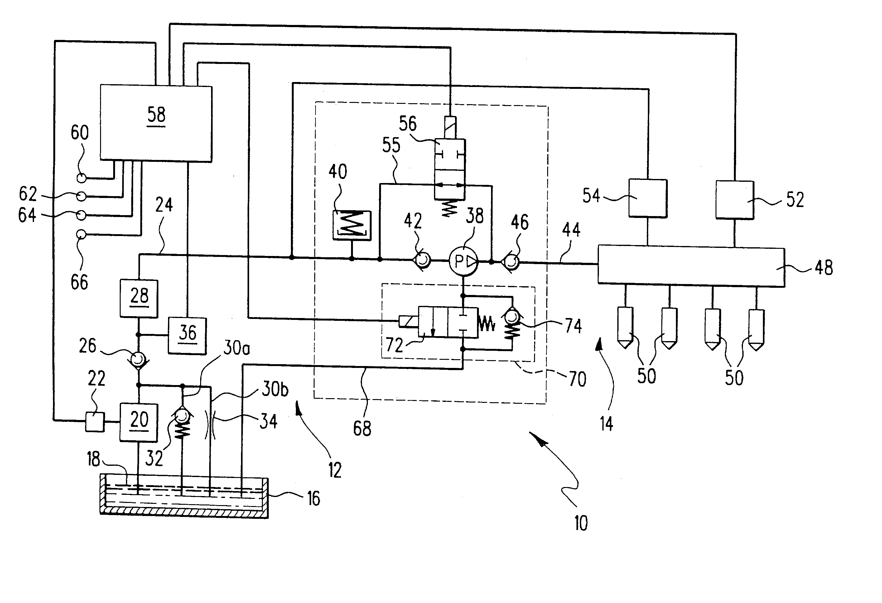
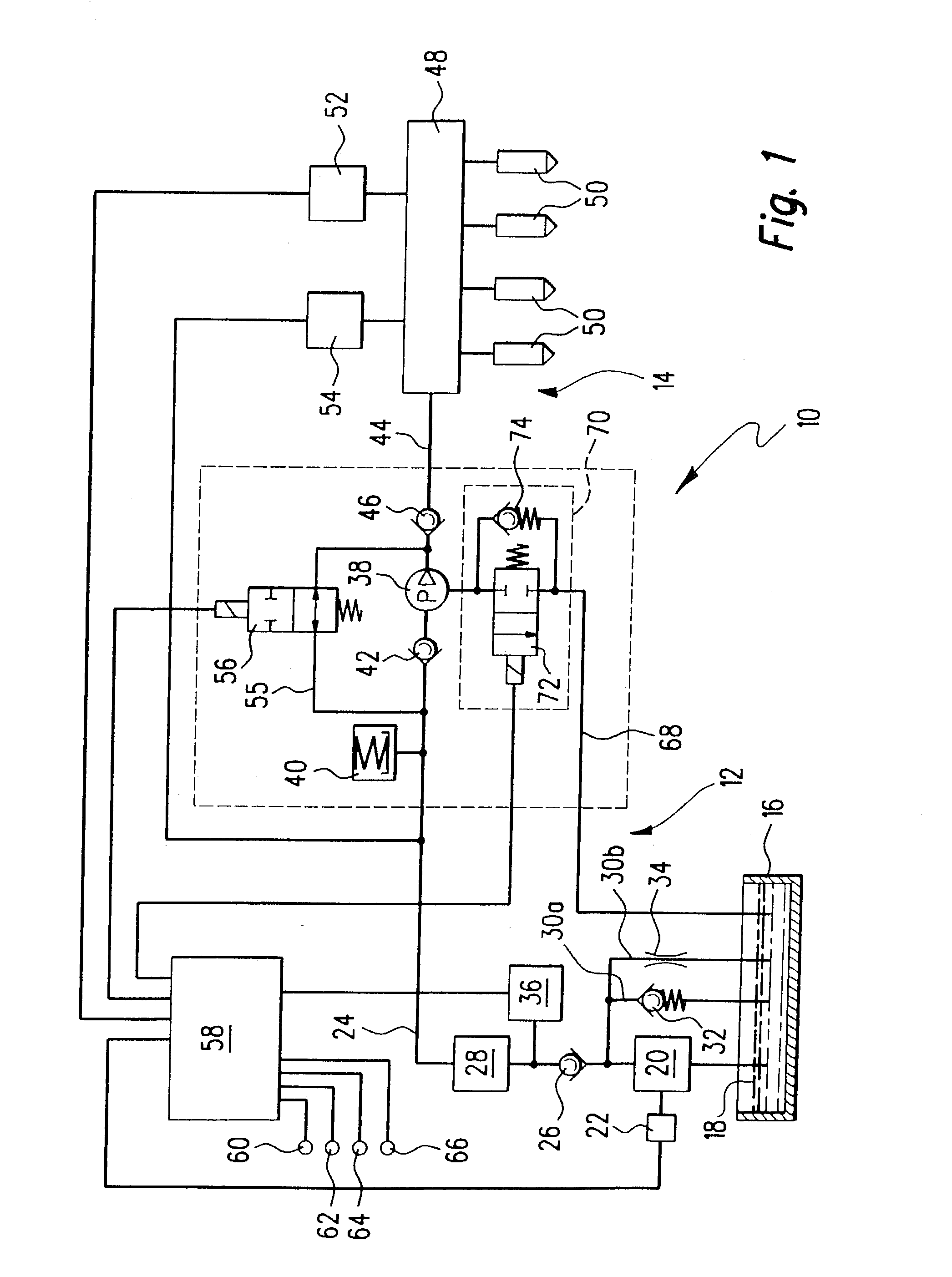
[0034] In FIG. 1, a fuel system is labeled as a whole with the reference numeral 10. It includes a low-pressure region 12 and a high-pressure region 14. First, the low-pressure region 12:

[0035] This region includes a reservoir 16 in which fuel 18 is stored. The fuel 18 is supplied from the reservoir 16 by a first fuel pump 20. This first fuel pump is an electric fuel pump, which is triggered by a clock module 22. The electric fuel pump 20 feeds into a low-pressure fuel line 24. Downstream of the electric fuel pump 20 in the flow direction, first a check valve 26 and then a filter 28 are provided. In the flow direction upstream of the check valve 26, a branch line 30 branches off from the low-pressure fuel line 24 and leads back to the reservoir 16. The branch line 30 splits into two parallel branches 30a and 30b. Branch 30a contains a pressure relief valve 32, while branch 30b contains a throttle 34. A pressure sensor 36 detects the pressure in the low-pressure fuel line 24.

[0036] T...


PUM


Abstract

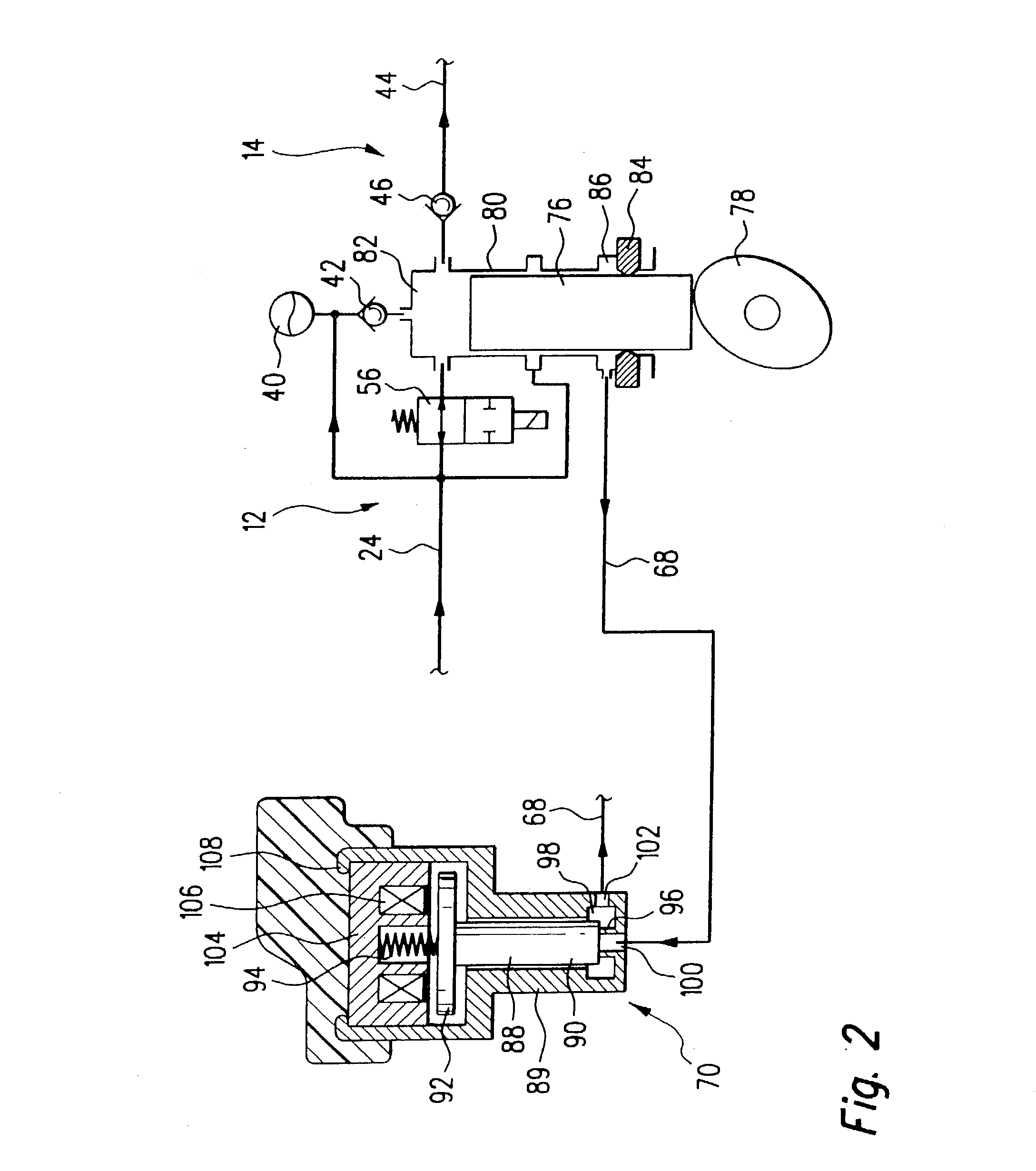
A fuel system (10) serves to supply fuel (18) to an internal combustion engine. The fuel system includes a reservoir (16) and a first fuel pump (20) whose input is connected to the reservoir (16). In addition, a second fuel pump (38) is provided, whose input is connected to the first fuel pump (20). Furthermore, at least one injection valve (50) is provided, which is connected to the second fuel pump (38) and can supply fuel at least indirectly to a combustion chamber. A leakage line (68) is provided between the second fuel pump (38) and the reservoir (16). In order to permit a reliable hot start of the engine with a simultaneously low strain on the components, the invention proposes that the leakage line (68) be provided with a valve device (70), which has a shutoff function (72) and a pressure relief function (74) that are connected in parallel with each other.

Description

PRIOR ART[0001] The invention relates first of all to a fuel system for delivering fuel to an internal combustion engine, with a reservoir, a first fuel pump whose input side is connected to the reservoir, a second fuel pump whose input side is connected to the first fuel pump, at least one injection valve that is connected to the second fuel pump and can supply fuel at least indirectly to a combustion chamber, and a leakage line provided between the second fuel pump and the reservoir.[0002] A fuel system of this kind is known from the market. In the known fuel system, a first fuel pump delivers fuel from a fuel reservoir to a second fuel pump by means of a fuel line. The second fuel pump is a high-pressure fuel pump, which delivers the fuel at a very high pressure into a fuel accumulation line (also referred to as the "rail"). From there, the fuel travels to at least one injection valve through which the fuel finally travels into the combustion chamber.[0003] Normally, the number o...

Claims


Application Information

Patent Timeline
IPC IPC(8): F02D33/00F02D41/04F02D41/06F02D41/38F02D45/00F02M37/00F02M37/20F02M55/02F02M59/36F02M59/42F02M59/44F02M59/46F02M63/02F04B23/04F04B53/04
CPCF02D33/006F04B53/04F02D41/3854F02D2200/0606F02D2250/02F02M37/0035F02M37/0047F02M37/0052F02M37/20F02M55/04F02M59/366F02M59/42F02M59/442F02M63/0225F04B23/04F02D41/042
Inventor REMBOLD, HELMUTWOLBER, JENSMUELLER, UWEAMLER, MARKUS
Owner ROBERT BOSCH GMBH
Learn More