Image receiving tube device

a technology of receiving tube and receiving tube, which is applied in the direction of cathode ray tube/electron beam tube, electromagnetic effect elimination, electric discharge tube, etc., can solve the problems of halving of the magnetic shield, degrading the magnetic shielding effect, and affecting the stability of the magnetic shield 1 to the frame 2 fixation, so as to achieve simple halation and low cost

Inactive Publication Date: 2003-08-21
PANASONIC CORP
View PDF2 Cites 0 Cited by
  • Summary
  • Abstract
  • Description
  • Claims
  • Application Information

AI Technical Summary

Benefits of technology

0015] The present invention aims to solve the above-mentioned conventional problems. More specifically, it is a first object of the present invention to provide a cathode ray tube capable of preventing the above-mentioned linear halation, which is liable to occur in a cathode ray tube with a particularly large total deflection angle of 115.degree. or more. Further, it is a second object of the present invention to provide a cathode ray tube capable of preventing halation simply and at low cost.

Problems solved by technology

Conventionally, it has been pointed out that the problem of halation is inherent in the cathode ray tube having the above configuration.
Besides, the end face 11 has a poor flatness, which causes the above-mentioned linear halation pattern having high visibility to appear in a particular portion of the screen, unlike the conventional halation pattern causing the entire screen to emit light uniformly.
Therefore, if the bent portion as disclosed in JP 5(1993)-314919 A is used to shield an overscanned electron beam, an electron beam for forming an image also is shielded, which brings about a problem that a shadow appears on the screen.
However, this results in reduction in area of the bent portion, which is provided on the screen 4 side of the magnetic shield 1 and is substantially perpendicular to the tube axis, and thus brings about the problems such as degraded magnetic shielding effect, degraded stability in fixing the magnetic shield 1 to the frame 2, and the like.
On the other hand, as a measure against halation in a cathode ray tube with a small deflection angle of 115.degree. or less, it is difficult to apply the method proposed in JP 2(1990)-244542 A to a cathode ray tube of a so-called tension-mask type, in which a shadow mask is stretched while being provided with a tensile force, because the degree of freedom in the shape of the frame is limited in such a cathode ray tube.
Further, the method proposed in JP 11(1999)-120932 A requires processing the inner surface of the shadow mask, resulting in high cost.
Besides, this method is not applicable to a cathode ray tube of a tension-mask type.
Furthermore, the method proposed in JP 5(1993)-314919 A does not provide any shielding effect on an electron beam passing through the portion other than the corner portion.

Method used


Image

  • Image receiving tube device
  • Image receiving tube device
  • Image receiving tube device

Examples


embodiment 2

[0071] (Embodiment 2)

[0072] Embodiment 1 has described the case where the present invention is applied to a color cathode ray tube of a so-called press-mask type, in which a dome-shaped shadow mask formed by press forming is held by a frame. The present embodiment will describe the case where the present invention is applied to a color cathode ray tube of a so-called tension-mask type, in which a flat shadow mask is stretched by a frame while being provided with a tensile force, or to a color cathode ray tube employing an aperture grille as a color selection electrode. The present embodiment also preferably is applied to a cathode ray tube with a total deflection angle of 115.degree. or more.

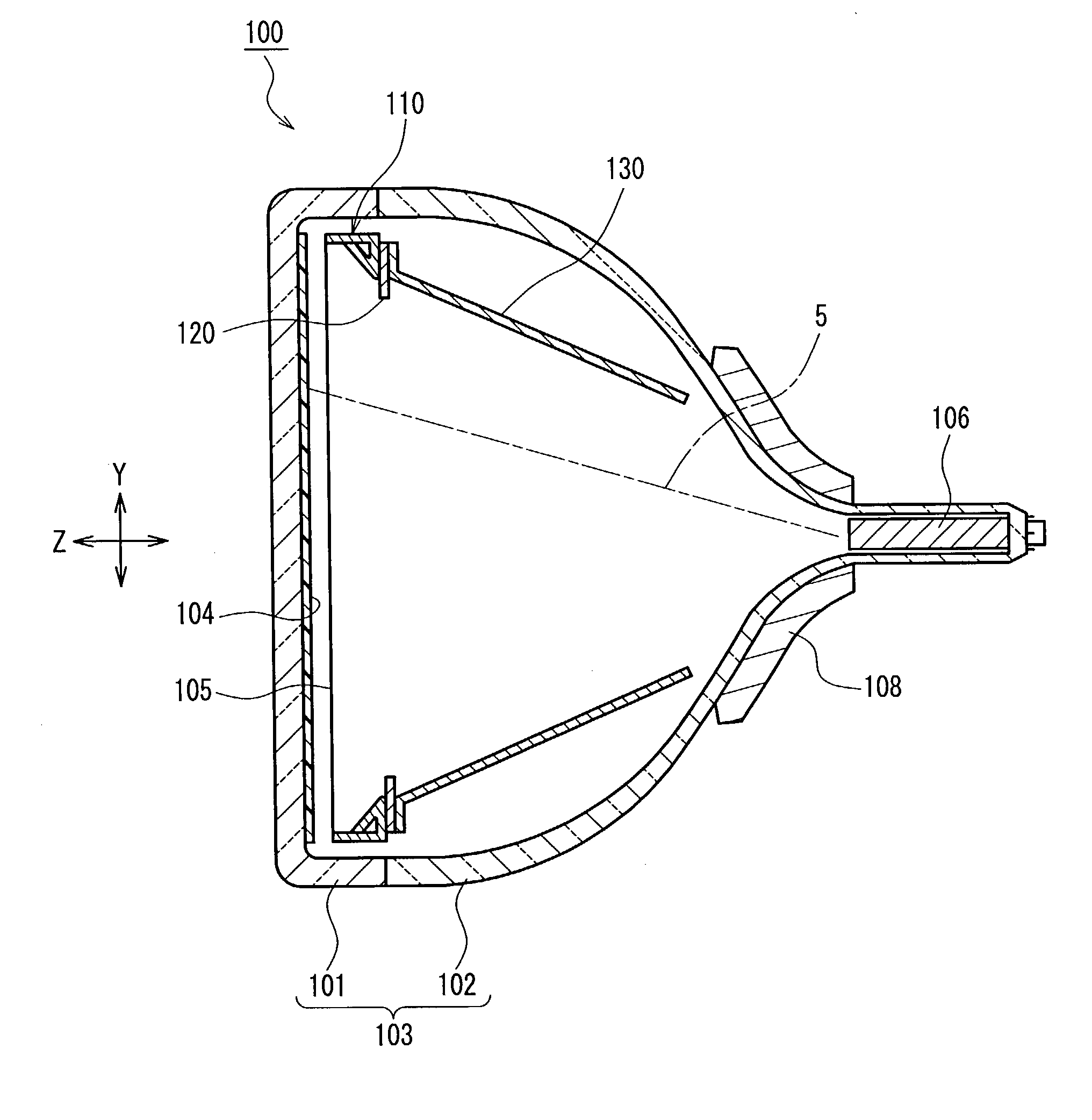
[0073] FIG. 3 is a cross-sectional view showing a color cathode ray tube 100 of a tension-mask type according to the present embodiment, the cross section shown in the drawing being a vertical plane taken on the tube axis. For convenience in the following explanation, as shown in FIG. 3, an XYZ-...

embodiment 3

[0096] (Embodiment 3)

[0097] In the present embodiment, one example of a color cathode ray tube preferably applied to a cathode ray tube with a total deflection angle of 115.degree. or less will be described while taking a cathode ray tube of tension-mask type as an example.

[0098] Since the general configuration of the color cathode ray tube of the present embodiment is substantially the same as that shown in FIG. 3 described in Embodiment 2, a description thereof has been omitted herein.

[0099] FIG. 9 is an exploded perspective view showing a configuration of a color selection structure according to Embodiment 3, which includes a frame 110, an electron shielding plate 120, and a magnetic shield 130. The color selection structure shown in FIG. 9 differs from the one shown in FIG. 4 only in the shape of the electron shielding plate 120. It is to be noted that components in common between FIG. 4 and FIG. 9 are numbered identically, and descriptions of these components have been omitted ...


PUM


Abstract

In a cathode ray tube including a panel provided with a phosphor screen, a funnel integrated with the panel, an electron gun disposed inside the funnel, a magnetic shield (1) for shielding an electron beam (5) emitted from the electron gun against an external magnetic field, and a frame (2) for holding the magnetic shield (1), the magnetic shield (1) includes, at a portion to be joined with the frame (2), a bent portion (20) bent toward a tube axis side, and a thickness T of the bent portion (20) at its edge on the tube axis side is 0.08 mm or less. By making the thickness T small, halation that is liable to occur in a cathode ray tube with a large deflection angle can be suppressed because electron beams reflected from an end face (11) and allowed to reach the screen without being shielded by the frame (2) are reduced.

Description

[0001] The present invention relates to a cathode ray tube.[0002] FIG. 12 is a cross-sectional view showing one example of a general configuration of a color cathode ray tube. As shown in FIG. 12, a color selection electrode (shadow mask) 3, a magnetic shield 1 for reducing the effect of the geomagnetism on tracks of electron beams 5, and a frame 2 for supporting the shadow mask 3 and the magnetic shield 1 are contained in an evacuated glass container formed of a panel 6 and a funnel 7. An electron gun 9 is contained in a neck portion of the funnel 7. Electron beams 5 emitted from the electron gun 9 are deflected by a deflection yoke 8 so that they pass through slot-shaped apertures formed on the shadow mask 3 and scan a rectangular phosphor screen 4 formed on the inner face of the panel 6.[0003] For convenience in the following explanation, as shown in FIG. 12, an XYZ-three dimensional rectangular coordinate system is defined, in which the X-axis is a horizontal axis perpendicular ...

Claims


Application Information

Patent Timeline
Patent Type & Authority Applications(United States)
IPC IPC(8): H01J29/06H01J29/18
CPCH01J29/06H01J29/185H01J2229/8634H01J2229/863H01J2229/003H01J29/02
Inventor YAMAUCHI, NAOKIIGUCHI, HIDEOOMAE, HIDEHARUKUMEI, YOSHIMIOZAWA, TETSUROKANNAN, YOKO
Owner PANASONIC CORP
Why Eureka
Try Eureka