Fluid dynamic pressure bearing for small flat motor, small flat motor, fan motor, and forced air feed type air cell

a technology of hydraulic bearings and flat motors, which is applied in the direction of liquid fuel engines, bearing unit rigid supports, machines/engines, etc., can solve the problems of imposing limits on efforts to reduce the overall height of the motor, the motor is not well suited to assembly in a mobile telephone, an electronic notebook or other portable information equipment, and the noise cannot be reduced to the near-zero level

Inactive Publication Date: 2003-09-04
NAMIKI PRECISION JEWEL CO LTD
View PDF14 Cites 23 Cited by
  • Summary
  • Abstract
  • Description
  • Claims
  • Application Information

AI Technical Summary

Problems solved by technology

In this fan motor, the bearing for the rotor is assembled with ball bearings, and so the rotor shaft of the rotor must be of some length, which imposes limits on efforts to reduce the overall height of the motor.
Further, because the ball bearings tend to produce noise and vibration, the motor is not well suited to assembly in a mobile telephone, an electronic notebook or other portable information equipment.
This small, flat motor produces less noise than that with ball bearings, but the noise cannot be reduced to the near-zero level.
This bearing also has the disadvantage of a shorter service life than ball bearings or dynamic pressure bearings.
This spiral spring mounting mechanism not only lacks stability in terms of stopping vibration of the motor as a whole in the event of impact, but it is also undesirable from the perspective of making the fan motor smaller and thinner as an assembled piece of equipment.

Method used


Image

  • Fluid dynamic pressure bearing for small flat motor, small flat motor, fan motor, and forced air feed type air cell
  • Fluid dynamic pressure bearing for small flat motor, small flat motor, fan motor, and forced air feed type air cell
  • Fluid dynamic pressure bearing for small flat motor, small flat motor, fan motor, and forced air feed type air cell

Examples


Embodiment Construction

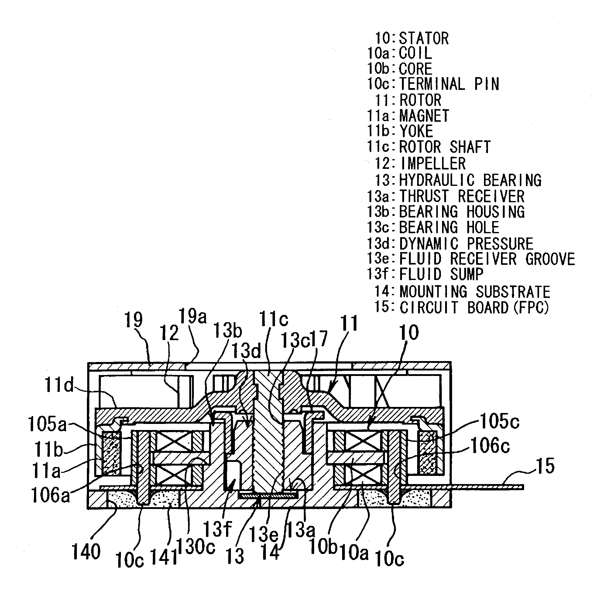
[0038] The explanation given below makes reference to the attached drawings. FIG. 1 shows a fan motor with a small, flat construction, as the optimum mode of implementation of this invention. This fan motor has a stator 10 with a coil 10a wound on a cores 10a . . . , and a rotor 11 on which a magnet 11a that faces the cores 10a . . . is held by a yoke 11b. An impeller 12 with an array of numerous fins is attached to the rotor 11, and the rotor 11 is supported, free to rotate, in a hydraulic bearing 13.

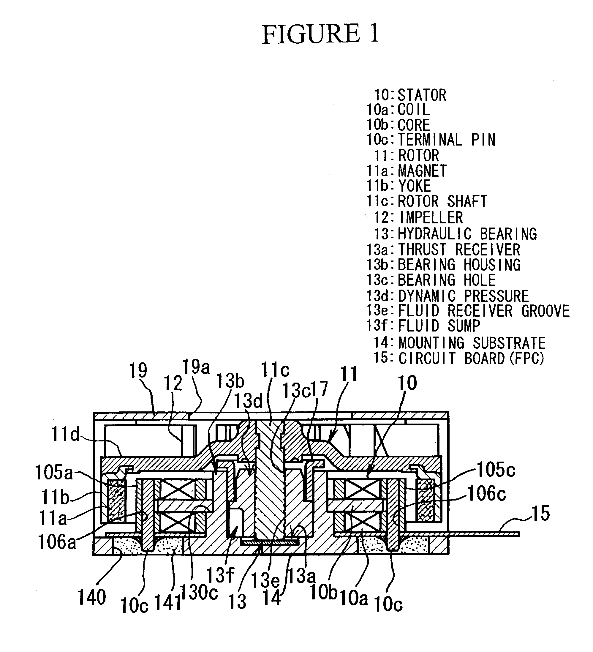
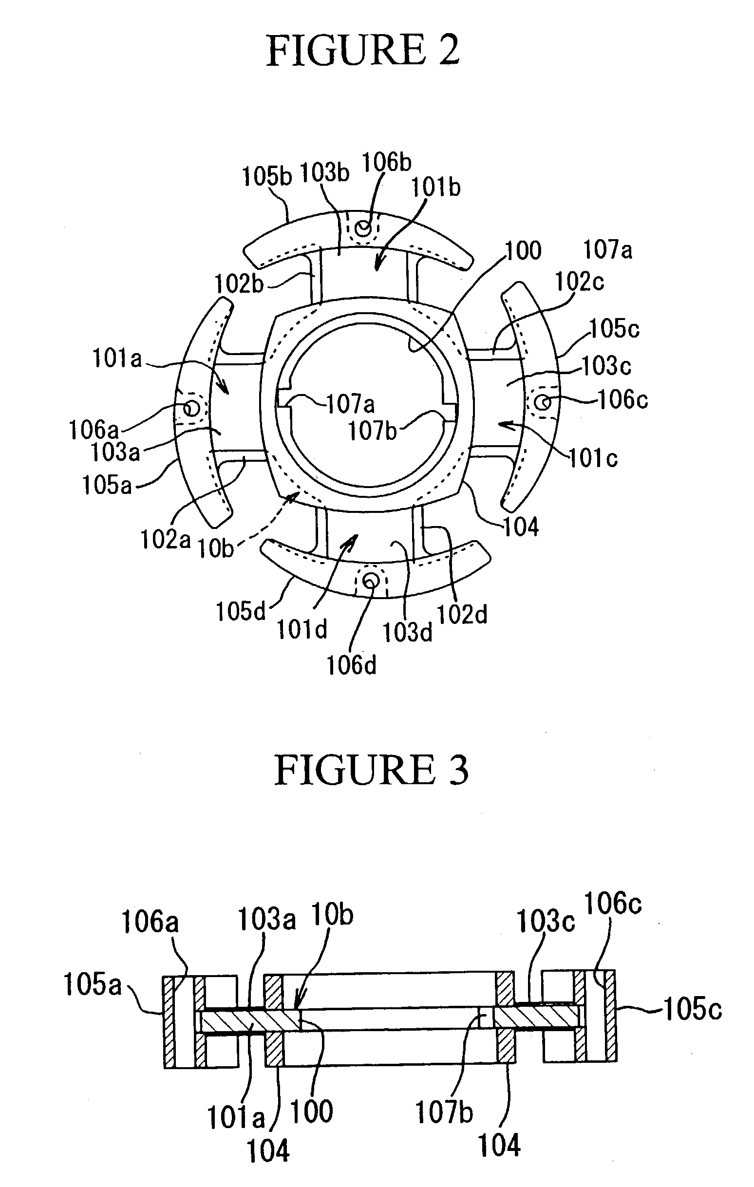
[0039] The stator 10 is assembled with a wing-shaped reel that is primarily the core 10b, as shown in FIGS. 2 and 3. This reel is made up primarily of the core 10b with a central ring 100 and multiple projections 101a to 101d that extend outward, separated by a fixed angle, from the periphery of the ring 100. the core 10b comprises a stack of multiple pieces punched from a sheet of silicon steel.

[0040] Within this core 10b, the projections 101a to 101d become the coil reel portion, and...


PUM

PropertyMeasurementUnit
thicknessaaaaaaaaaa
timeaaaaaaaaaa
flexibleaaaaaaaaaa

Abstract

This invention has a stator 10 having a coil 10a wound on a core 10b, a rotor 11 having a yoke 11b that holds a magnet 11a facing the core 10a, in which an impeller 12 is attached to the rotor 10 that is supported by a hydraulic bearing 13 having a fluid sump 13f that communicates with the thrust receiver 13a of a bearing housing 13b and a fluid receiver groove 13c, and that is formed around the outer periphery of a hydraulic sleeve 13d fitted within the inner cylinder of the bearing housing 13b.

Description

[0001] Hydraulic bearing for a small, flat motor; small, flat motor; fan motor; and forced-air air cell.SCOPE OF PATENT CLAIMS[0002] This invention concerns improvement of a hydraulic bearing for a small, flat motor; small, flat motor; fan motor; and forced-air air cell.FIELD OF TECHNOLOGY[0003] This invention concerns improvement of hydraulic bearings for small, flat motors; small, flat motors; fan motors; and forced-air air cells.PRIOR ART[0004] Taking fan motors as one example of small, flat motors, a proposal has been made previously to make a fan motor with a stator that has a coil wound around a core, a rotor in which a magnet facing the core is held by a yoke, an impeller attached to the rotor, and a bearing seat with ball bearings that supports the rotor shaft of the rotor, in which the interaction of magnetic force of the magnet and the electromagnetic force of the coil produce the rotational force of the rotor (JPO Kokai patent report H6-141507).[0005] In this fan motor, t...

Claims


Application Information

Patent Timeline
Patent Type & Authority Applications(United States)
IPC IPC(8): F04D29/04F04D29/051F04D29/057F16C17/02F16C17/08F16C33/08F16C33/10F16C35/02H01M12/00H01M12/06H02K1/04H02K3/18H02K3/52H02K5/16H02K5/167H02K5/22H02K5/24H02K7/08H02K7/14H02K11/00H02K11/04
CPCF04D29/051F04D29/057F16C17/026F16C17/045F16C33/103H02K29/03H01M12/00H02K5/1675H02K5/22H02K5/24H02K11/0073F16C33/107H02K11/33F04D29/0513
Inventor YASUDA, HISAFUMI
Owner NAMIKI PRECISION JEWEL CO LTD
Why Eureka
Try Eureka