Cylindrical magnetic recording medium and method for manufacturing the same

a technology of cylindrical magnetic and recording medium, which is applied in the direction of magnetic materials for record carriers, instruments, record information storage, etc., can solve the problems of large bit volume, small leakage field, and undetected leakage field

Inactive Publication Date: 2003-09-11
CANON KK
View PDF0 Cites 5 Cited by
  • Summary
  • Abstract
  • Description
  • Claims
  • Application Information

AI Technical Summary

Problems solved by technology

However, in the longitudinal recording method, when bit length is shortened to improve recording density, the leakage field from the magnetization transfer regions becomes smaller, which causes the leakage field to be undetected when the bit length is minuscule.
Although this problem can be avoided by making the film thickness of a magnetic layer thinner, this in turn caus

Method used


Image

  • Cylindrical magnetic recording medium and method for manufacturing the same
  • Cylindrical magnetic recording medium and method for manufacturing the same
  • Cylindrical magnetic recording medium and method for manufacturing the same

Examples


embodiment examples

[0056] (Embodiment 1) Manufacture of Cylindrical Magnetic Recording Medium:

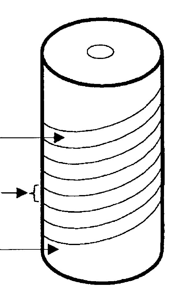
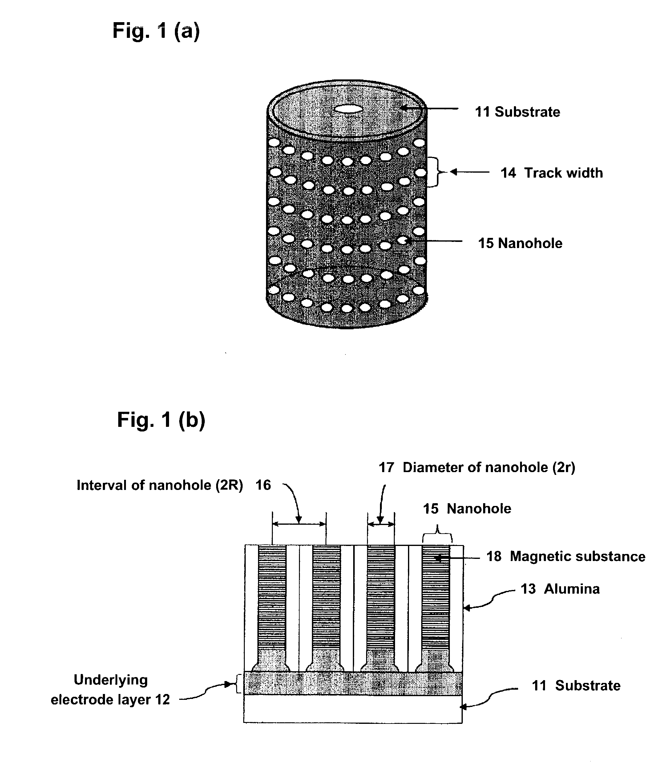
[0057] First, the sputtering method was used to form a 50 nm Cu film and a 500 nm Al film on the outer circumference surface of a cylindrical glass substrate. Next, the substrate was anodized by applying a voltage of40 V at 16.degree. C. in a 0.3 M oxalic acid aqueous solution, and nanoholes were formed on the outer circumference surface of the cylindrical glass substrate. As a porewidening processing to enlarge the diameter of the nanoholes formed, a wet etching, in which the substrate was immersed in a 0.5 wt % phosphoric acid aqueous solution for 40 minutes, was rendered.

[0058] Co with an hcp structure whose c axis is oriented towards the center axis of the cylinder shape, i.e., in the radial direction, was embedded in the nanoholes formed according to the procedure described above through electrodeposition. In the electrodeposition, a mixed solution of 0.2 M of cobalt sulfate (II) heptahydrate and 0.3 M o...

embodiment 2

[0062] (Embodiment 2) Manufacture of Nanoholes Using a Stamper:

[0063] First, a stamper with protrusions aligned in a honeycomb shape on the surface of a flat substrate was prepared. Next, a cylindrical substrate on which an Al film is formed as in Embodiment 1 was prepared, and the protrusion pattern of the stamper was transferred onto the outer circumference surface of the cylindrical substrate. In the transfer, a cylindrical substrate support section 61, as shown in FIG. 7, was provided in the center of a cylindrical substrate 62; using the cylindrical substrate support section 61 as a shaft, the cylindrical substrate 62 was rolled to press down on the surface of a stamper 64 with protrusions 63. Through this step, the protrusions 63 of the stamper 64 were transferred as depressions on the outer circumferential surface of the cylindrical substrate 62. The cylindrical substrate on which were formed honeycomb-structured depressions on its outer circumference according to the procedu...


PUM


Abstract

A magnetic recording medium includes a cylindrical substrate and pores embedded with a magnetic substance that are provided on the outer circumferential surface of the cylindrical substrate and aligned in tracks that are in parallel with one another along the center axis of the cylindrical substrate. The tracks have as their center the center axis of the cylindrical substrate, and form circular orbits defined by planes perpendicular to the center axis. Alternatively, the tracks are in a spiral orbit or in spiral orbits whose center is the center axis of the cylindrical substrate. The pores at intersections of vertical and horizontal rows are aligned in quadrilaterals such as squares, rectangles or rhombi.

Description

[0001] 1. Field of the Invention[0002] The present invention relates to a cylindrical magnetic recording medium called a patterned medium with a constant track length, a constant recording bit number in each track and high recording density, and to a method for manufacturing the cylindrical magnetic recording medium.[0003] 2. Related Background Art[0004] As indicated by high density / large capacity trend in hard disks in recent years, the recording density of magnetic recording media continues to increase at an astonishing annual rate of 60%-100%, and a case has even been reported in which a recording density of over 50 GB / in..sup.2 was achieved. However, further progress is anticipated, and while numerous vigorous research and development efforts continue in this area, an interest in the next generation magnetic recording medium is rising.[0005] At present, the longitudinal recording method in which magnetization is recorded in the direction that follows along a recording surface is...

Claims


Application Information

Patent Timeline
IPC IPC(8): G11B5/004G11B5/65G11B5/667G11B5/73G11B5/76G11B5/84G11B5/855G11B5/858
CPCG11B5/855
Inventor SAITO, TATSUYADEN, TOHRU
Owner CANON KK
Why Eureka
Try Eureka