Fuel cell stack

Inactive Publication Date: 2003-09-18
FORSCHUNGSZENTRUM JUELICH GMBH
View PDF3 Cites 7 Cited by
  • Summary
  • Abstract
  • Description
  • Claims
  • Application Information

AI Technical Summary

Benefits of technology

[0014] This arrangement has the effect, by contrast with the earlier state of the art, that in the regions of the passage of each individual element to its neighboring element which formally required sealing, a seal can be avoided. As a result, the fuel cell stack is advantageously correspondingly constructed in a more compact manner. The requisite layer thickness of a single fuel cell and thus of the total fuel cell stack can be reduced as a rule.
[0015] For more than three elements, there is a saving not only of one, but of a correspondingly larger number of additional seals. The advantageous reduction in the layer thickness for an individual fuel cell grows with each seal which is saved.
[0016] In an advantageous embodiment of the invention, the outwardly lying elements have passages with the same diameter. These passages usually form a part of a channel for the operating media. These can advantageously have a single diameter so that flow changes and pressure changes because of different geometries can be avoided.
[0017] Advantageously, also all of the inwardly lying elements can have identical diameters for their passages. These passages should be selected to be so large that a seal inserted between the outwardly lying elements can be so dimensioned that its inner diameter corresponds with that of the outwardly lying elements. This advantageously results in a substantially frictionless transition of sealing to breakthrough within the passage for the operating media.
[0020] The layer thickness can be reduced especially effectively when in a fuel cell stack as many of the operating medium passages as possible can be sealed. Advantageously a fuel cell stack should have elements with at least two and advantageously however, four passages for the formation of operating medium passages. They can be arranged diagonally in an element to achieve an optimum distribution of the operating medium in the electrode compartment.
[0021] Additional passages in several elements, especially the flat seals give rise advantageously to a simple electrical contacting between two non-directly neighboring elements. The contact between these elements is effected not externally of the elements but through suitable means directly between them. One such suitable means is a conductive lug which can be swung out of the plane of a first element. Through the corresponding passage in the neighboring second element, there is no contact with this element. Only the further, third element, which has no passage at the corresponding location is contacted by the lug so that in a simple way an electrical connection between the first and third elements but not, however, to the intermediate element, can be made.SPECIAL DESCRIPTION PART

Problems solved by technology

Up to now, for the cell frames and also the bipolar plates, expensive structures have actually been required and have been complicated to fabricate and have a certain minimum structural height.
Disadvantageously, this bipolar plate requires sealing between the individual components.
It has also been found to be a drawback with this configuration that both the anode and cathode components and also the passages through which the operating substances must pass, must be sealed.
Because of the compact configuration of the fuel cell stack, the seals which are typically used are flat seals which mandate high requirements for the surfaces of the components as to roughness and finishing precision and thus usually give rise to higher fabrication costs.

Method used


Image

  • Fuel cell stack
  • Fuel cell stack
  • Fuel cell stack

Examples


first embodiment

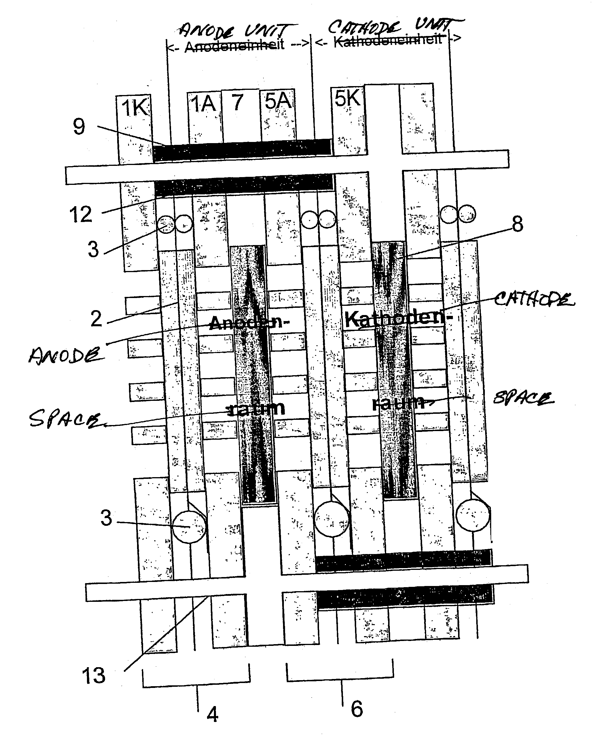
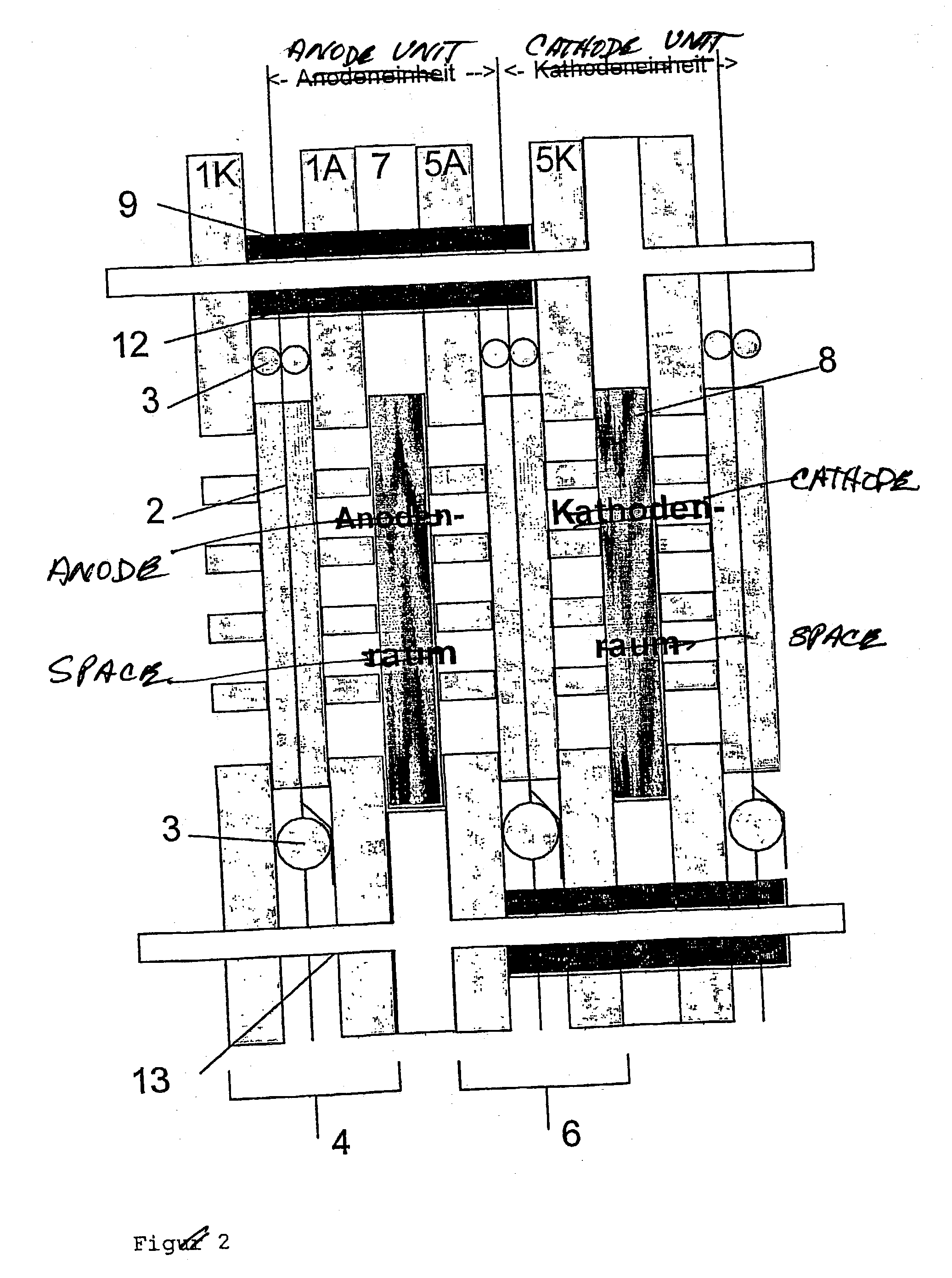
[0040] FIGS. 3a through 3c show in a first embodiment the construction of a fuel cell stack according to the invention from individual elements. The membrane-electrode units (MEAs) 2 are premounted in cartridges 4, 6. The electrical insulation of the cartridge plates 1 to 5 are effected over an MEA flat seal 3. The cartridges 4, 6 are so arranged in the stack that if two cartridges are in contact over a common anode compartment or cathode compartment. The anode compartment or the cathode compartment between two cartridges 4, 6 or one compartment 4, 6 and an end plate 10, 11 is formed by a cutout 7b in the flat seal 7. The flow distribution within the medium compartments and the tightening of the MEA can be realized by nonconducting inserts 8.

[0041] The insert 8 is a plastic fabric. The cartridge plate 1 and 5 connect via bores 1a, 1b, 5c, 5d into operating medium ducts. The bores 1a, 5c are smaller than the bores 1b, 5d.

[0042] The sealing of the medium ducts form, for example, one a...

second embodiment

[0043] FIGS. 4a through 4c show in a second embodiment the construction of a fuel cell stack of the invention from individual elements. In contrast to the fuel cell stack shown in FIG. 3, the individual cartridges 4 and 6 have in this embodiment in their individual elements 1 and 5 only 2 each of through openings. The through openings for the oxidizing medium passage are omitted. Further, instead of flat seal 7 with inserts provided in the recesses 7b of plastic fabric, partial flat seals 7 (8) are provided which now are completely comprised of the fabric 8 and have through openings for the fuel passage as well as for the lugs 5a.

[0044] Instead of a continuous oxidizing agent passage, the oxidizing agent in this embodiment flows directly from the edges of the flat seal 7 (8) into the corresponding cathode compartment. The oxidizing agent is then conducted via blowers into the fabric 7 (8). For small powers it suffices to provide a fabric 7 (8) of a thickness of 2 to 4 mm without a b...


PUM


Abstract

The invention relates to a fuel cell stack in which, according to the invention, several elements of the fuel cell stack are advantageously sealed by a seal in order to form a continuous operating material channel. The inventive fuel cell stack can be provided with a very compact design, whereby the layer thickness of an individual fuel cell is, on a regular basis, distinctly less than 1.5 mm and, advantageously, even less than 1.2 mm.

Description

[0001] The invention relates to a fuel cell stack, especially for low-temperature fuel cells.STATE OF THE ART[0002] A fuel cell has a cathode, an electrolyte, and an anode. The cathode is supplied with an oxidizing medium, for example, air, and the anode is supplied with a fuel, for example, hydrogen.[0003] Different fuel cell types are known, for example, the SOFC fuel cell of the publication DE 44 30 958 C1 and the PEM fuel cell of the publication DE 195 31 852 C1.[0004] A plurality of fuel cells are, as a rule, electrically and mechanically connected together in order to produce greater electrical powers by connecting elements. An example of such a connecting element is the bipolar plate which is known from DE 44 10 711 C1. By means of bipolar plates, fuel cells stacked one above another are connected electrically in series. This arrangement is termed a fuel cell stack.[0005] By providing common anode and cathode compartments for respective pairs of fuel cells, the space required...

Claims


Application Information

Patent Timeline
IPC IPC(8): H01M8/241H01M8/2465H01M8/2485
CPCH01M8/241Y02E60/50H01M8/2485H01M8/2465H01M8/2483
Inventor DOHLE, HENDRIKBEWER, THOMAS
Owner FORSCHUNGSZENTRUM JUELICH GMBH
Why Eureka
Try Eureka