Device for reliably generating signals

a technology of reliably generating signals and devices, applied in the direction of electric controllers, electric control, instruments, etc., to achieve the effect of increasing the reliability of the entire system

Inactive Publication Date: 2003-09-25
ROBERT BOSCH GMBH
View PDF13 Cites 3 Cited by
  • Summary
  • Abstract
  • Description
  • Claims
  • Application Information

AI Technical Summary

Benefits of technology

[0003] The device of the present invention for reliably generating signals includes a control means, which receives a control signal. The control means generates a trigger signal as a function of the control signal, in order to trigger a load. The present invention provides for emergency operating means, which generate the trigger signal in place of the control means during emergency operation. The redundant generation of the trigger signal increases the reliability of the entire system, since, in the case of the control means malfunctioning, the emergency operating means are still available for generating the trigger signal in an emergency operation. This ensures correct triggering, in particular in the case of signals that are critical with regard to safety, such as the terminal control signal for an ignition switch. When errors occur in a component in the system, the trigger signal does not change into an incorrect state, and may also not be switched over into another state. To accomplish this, the control signal is to be advantageously supplied to the emergency operating means as well, which generate the trigger signal from this control signal during emergency operation.
[0004] An advantageous further refinement provides triggering means, which are used to activate the emergency operating means and activate the emergency operating means when a fault is detected in the control means. The switchover to emergency operation and the corresponding control by the emergency operating means is only carried out in an emergency. However, the control means continues to generate the trigger signal during normal operation. This allows the complexity of the emergency operating means to be reduced, since, in normal operation, the control means assumes the normally more complex functionality.

Problems solved by technology

However, if a signal critical with regard to safety is generated by a microcontroller, it must be ensured that its safety-critical output signal does not change into an incorrect state or can no longer be switched over from the one state to another state, when a single-chance fault occurs.

Method used


Image

  • Device for reliably generating signals
  • Device for reliably generating signals

Examples


Embodiment Construction

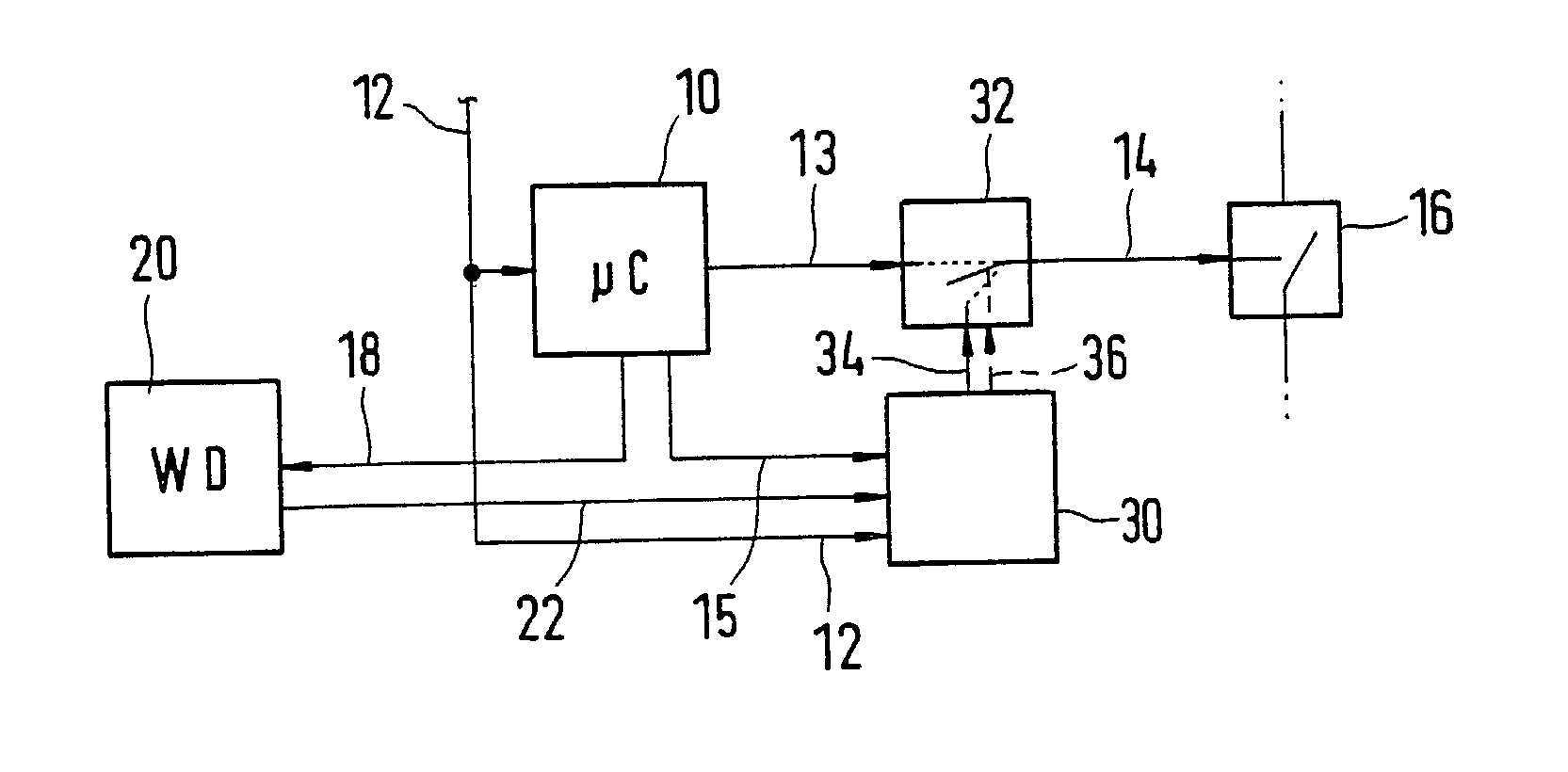
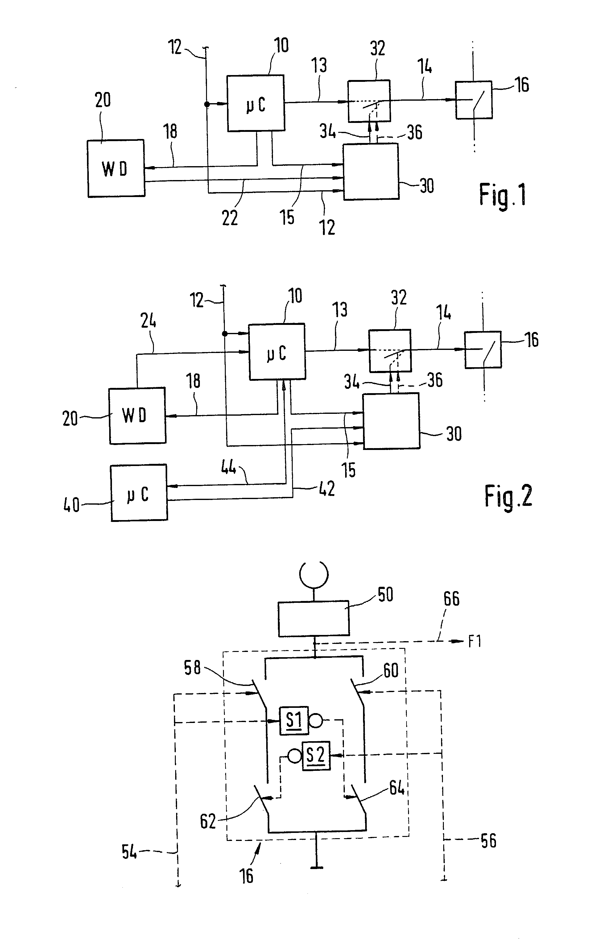
[0008] A control signal 12 is supplied to a control means 10 and an emergency operating means 30. Control means 10 generates an output signal 13, which is supplied to emergency-operation switching element 32. A trigger signal 18 supplied by control means 10 is processed by a monitoring means 20. Control means 10 also generates an emergency-operation trigger signal 15 for emergency operating means 30. Emergency operating means 30 also receives a monitoring output signal 22 generated by a monitoring means 20. Emergency operating means 30 generates an emergency-operation output signal 34 and an emergency-operation control signal 36. The switch position of emergency-operation switching element 32 may be changed, using emergency-operation control signal 36. In the one switch position, emergency-operation switching element 32 transmits output signal 13 of control means 10 to a switching element 16, in the form of trigger signal 14. In the other switch position, emergency-operation switchi...


PUM


Abstract

A device for reliably generating signals, which includes a control means (10) that is supplied a control signal (12). The control means (10) generates a trigger signal (13, 14) as a function of the control signal (12), in order to trigger a load (50). Emergency operating means (30, 32) are provided, which, in an emergency operation, generate the trigger signal (34, 14) as a function of the control signal (12).

Description

BACKGROUND INFORMATION[0001] The present invention starts out from a device for reliably generating signals according to the species defined in the independent claims. In today's systems, signals that are critical with regard to safety, such as terminal control signals of an ignition switch, are directly transmitted to the signal drain. However, if a signal critical with regard to safety is generated by a microcontroller, it must be ensured that its safety-critical output signal does not change into an incorrect state or can no longer be switched over from the one state to another state, when a single-chance fault occurs.[0002] Therefore, the object of the present invention is to increase the reliability of preparing the signal, using a microcontroller. This object is achieved by the features of the independent claims.[0003] The device of the present invention for reliably generating signals includes a control means, which receives a control signal. The control means generates a tri...

Claims


Application Information

Patent Timeline
Patent Type & Authority Applications(United States)
IPC IPC(8): F02D41/22F02N11/08G05B9/02G05B23/02H01H27/00
CPCF02D2041/2072F02N11/0803F02N11/087F02N11/10F02P1/08H01H2009/0083F02P3/0846G05B9/02G05B9/03H01H27/00F02P3/0442
Inventor SCHENK, JOACHIMBREUNIG, VOLKERSCHMIDT, FRANKMAHLER, ACHIMWENZEL, KARLOWERFELDT, ANDRE
Owner ROBERT BOSCH GMBH
Why Eureka
Try Eureka