

Optical transmission systems
- Summary
- Abstract
- Description
- Claims
- Application Information
AI Technical Summary
Benefits of technology
Problems solved by technology
Method used
Image

Examples
Embodiment Construction
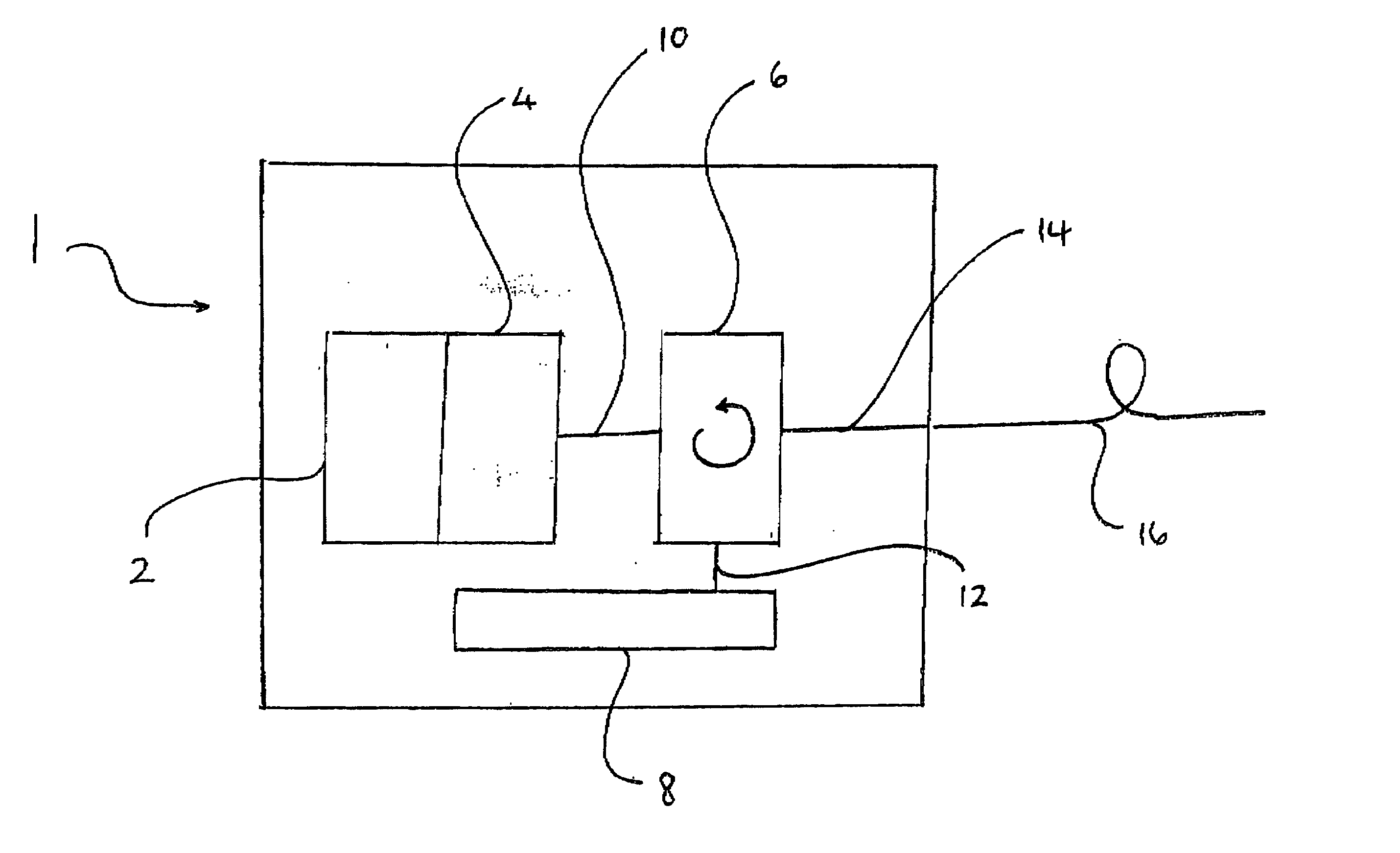
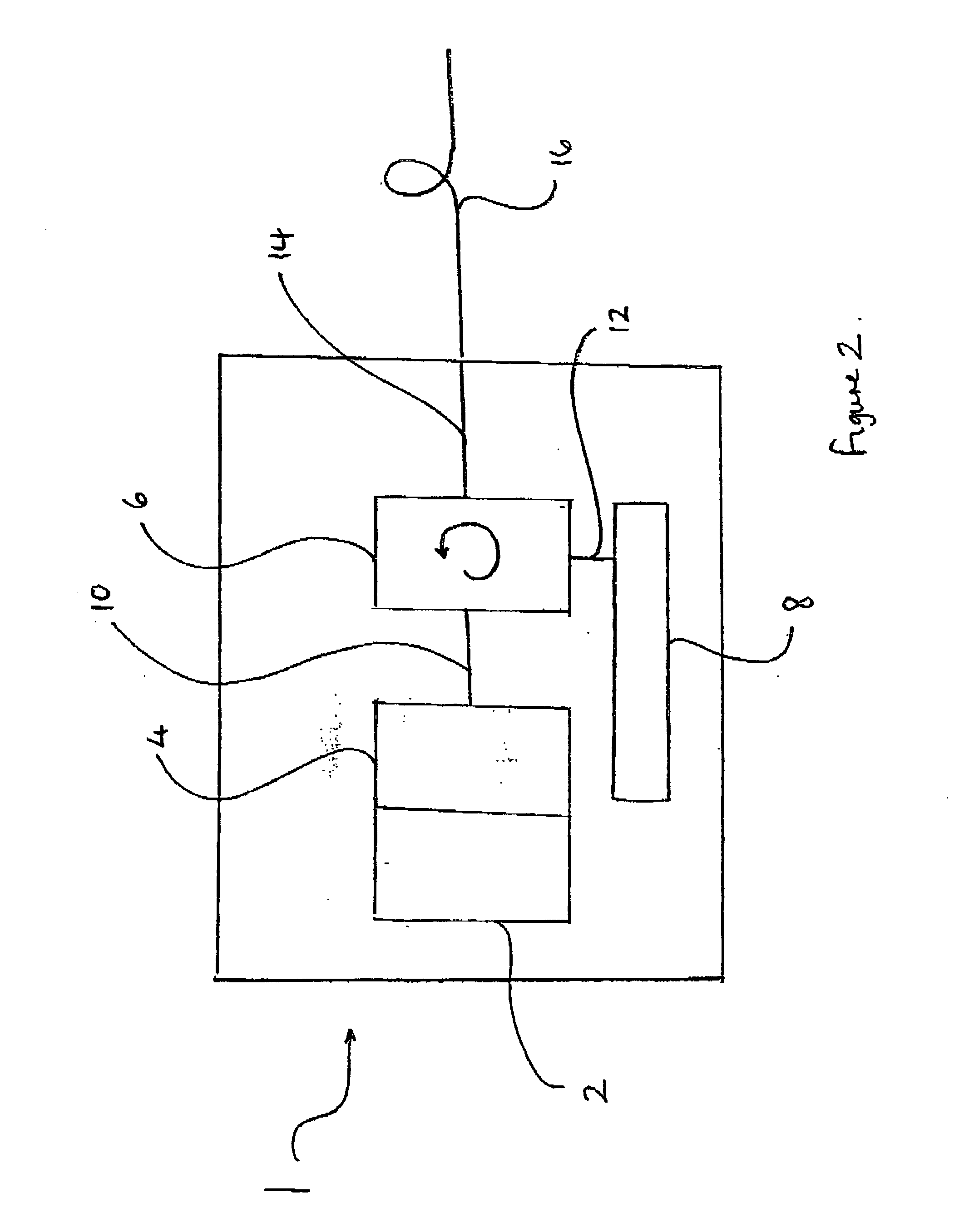
[0066] With reference to FIG. 2, a transmitter module 1 has an optical source 2, a modulator 4, coupling means 6 and a dispersion element 8. An output 10 from the modulator 4 is input to the coupling means 6. An input / output 12 from the coupling means 6 is connected to the dispersion element 8. An output 14 from the coupling means 6 is connected to a NDSE 16.
[0067] In the specific embodiment illustrated, the optical source 2 and the modulator 4 are a 10 Gbits / s DFB-electro absorption integrated laser modulator (ILM). The laser wavelength is positioned in relation to the edge of the ILM modulator absorption band so as to introduce pure positive chirp. A chirp factor a is also selected, in this specific case of +0.7. The coupling means 6 is a three port circulator. The dispersion element is a linear chirped fibre Bragg grating (FBG) which has a bandwidth to fully cover the wavelength channels of interest but with sufficient guard bandwidth to cover any wavelength detaining effects tha...
PUM
 Abstract
Description
Claims
Application Information