Imprint method and device

a printing method and printing technology, applied in the field of printing methods and devices, can solve the problems of high consumption of pressure medium, difficult to make it compatible with clean rooms, and limit the cycle tim

Active Publication Date: 2003-10-09
OBDUCAT AB SE
View PDF14 Cites 163 Cited by
  • Summary
  • Abstract
  • Description
  • Claims
  • Application Information

AI Technical Summary

Problems solved by technology

A problem that is common for all nanoimprint lithography processes is that the pressure, i.e. the force across the respective surfaces need to be uniform, so that the relief pattern is uniformly transferred to the substrate.
U.S. Pat. No. 5,772,905 discloses some fundamental principles of nanoimprint lithography, but does not discuss the problem of parallelization, nor does it disclose any practical embodiments of a printing apparatus.
A disadvantage with a device using hydraulic oil is, however, that it is difficult to make it compatible with clean rooms, in which imprinting machines are frequently to be placed.
This first type of nanoimprint lithography device has drawbacks from a productivity point-of-view: insertion and removal of the aggregate in the pressure chamber is time consuming; the time it takes to fill up the pressure chamber will limit the cycle time; and the consumption of pressure medium is high.
When gas is used as a pressure medium and a leak arises due to e.g. a template breaking, the compressed gas housed in the pressure cavity may rapidly expand and may sometimes cause an explosion-like condition, which may damage adjacent equipment or, at worst, personnel working near the lithography device.
A s

Method used


Image

  • Imprint method and device
  • Imprint method and device
  • Imprint method and device

Examples


first embodiment

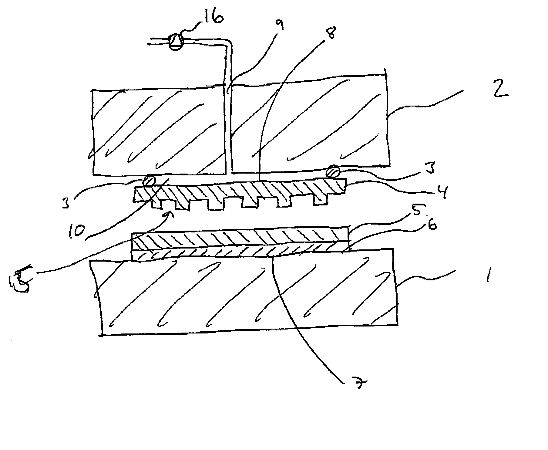
[0050] FIG. 1 is a schematic cross sectional view of the invention. In FIG. 1, a first support member 1, and a second support member 2 are arranged to support a substrate 6 and a template 4, respectively. The substrate 6 and the template 4 may be sheet-like structures, i.e. having two major surfaces and a relatively thin cross section. At least one of the major surfaces is the active surface, i.e. the surface having the relief pattern in the case of the template and the surface having the moldable film, in the case of the substrate. The thickness of the template and the substrate may be constant, but it may also vary, as long as the active surfaces remain essentially plane.

[0051] The support members 1, 2 may be movable relative each other in order to enable the insertion and removal of the substrate 6 and the template 4. In the embodiment shown in the enclosed drawings, the substrate is arranged horizontally on a lower support member 1, while the template is arranged horizontally on...

second embodiment

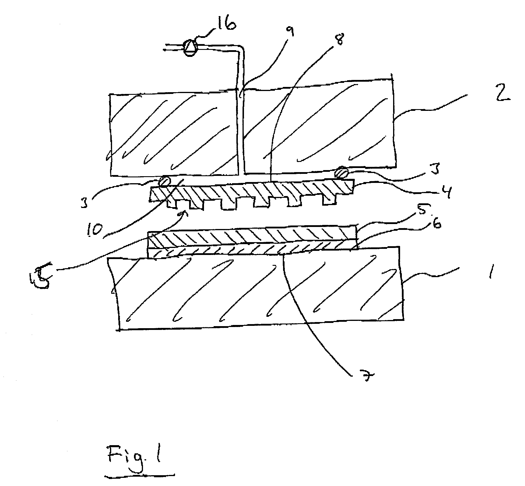
[0063] FIG. 4 is a schematic cross sectional of the invention The embodiment of FIG. 2 essentially corresponds to the embodiment shown in FIG. 1, except for the addition of a recess 11 in the surface of the support member 2. The recess functions so as to increase the distance d between the surface of the support member 2 and the template back surface 8, Thus, the pressure cavity is defined by the template back surface 6, the sealing gasket 3 and the recess. It is realized that the recess does not need to have a uniform depth, but may have any suitable shape. Also, the recess may cover a surface area that is equal to the area provided with the relief pattern, or a smaller area. It may be provided with e.g. grooves for controlling airflows within the cavity.

third embodiment

[0064] FIG. 5 is a schematic cross sectional view of the invention, wherein multiple, in this case two sealing gaskets 3, 13 are arranged between the template and the surface of the second support member 2. This embodiment is particularly suitable when the substrate and / or the template has a through hole, such as is the case with e.g. compact discs (CD) or digital versatile discs (DVD).

[0065] In this embodiment, the pressure cavity is defined by the surface of the support member 2, the template back surface and the two sealing gaskets 3, 13. Thus the pressure is provided only in the area where the relief pattern 15 is situated, and there is no pressure provided in the area where the hole is. This enables processing of templates and / or substrates having a through hole, without losing pressure. This may also prevent the template from being damaged by the contact with the edges of the holes.

[0066] Also in this embodiment, it is possible to provide a recess in the support member 2 surfa...


PUM

PropertyMeasurementUnit
Lengthaaaaaaaaaa
Lengthaaaaaaaaaa
Lengthaaaaaaaaaa

Abstract

An imprint process comprises the step of aligning a substrate, supported on a first support member, with a template, supported on a second support member. The substrate has at least one essentially plane surface provided with a moldable film. The template has at least one essentially plane surface provided with a relief pattern. The relief pattern is adapted to interact with the moldable film. The process further comprises the step of arranging a sealing gasket between the template and the second support member, such that a pressure cavity is defined by the second support member, the template and the sealing gasket. The process also comprises the step of applying a static gas pressure to the pressure cavity, in order to provide a pressure between the template and the substrate. The pressure is sufficient to form a pattern in the moldable film. An imprint device is also disclosed.

Description

[0001] The present invention relates to an imprint process and device. More specifically, the present invention relates to a process and a device which is suitable for nanoimprint lithography and embossing.PRIOR ART[0002] In many contexts it is desirable to provide small structures in the surface of a material. A method for providing such small structures is nanoimprint lithography. Known methods and devices for nanoimprint lithography are described in U.S. Pat. No. 5,772,905 and WO01 / 42858A1, which are hereby incorporated by reference. Another known method is disclosed in WO02 / 07199A1.[0003] Nanoimprint lithography typically utilizes a printing process, wherein a relief pattern is formed in the surface of a template and transferred onto a moldable film which is arranged on a substrate. The moldable film is subjected to e.g. removal of reduced thickness portions, which exposes the underlying part of the substrate for further processing. The process of transferring the relief pattern...

Claims


Application Information

Patent Timeline
IPC IPC(8): B29C43/02B29C43/10B29C43/36B29C59/02G03F7/00G11B7/26
CPCB29C43/021B29C43/10B29C43/3642B29C59/022B29C59/026G11B7/263B29C2791/006B82Y10/00B82Y40/00G03F7/0002B29C2059/023
Inventor OLSSON, LENNART
Owner OBDUCAT AB SE
Why Eureka
Try Eureka