Dosing system for inking up rollers in a printing machine

Inactive Publication Date: 2003-10-16
MANROLANAD AG
View PDF6 Cites 3 Cited by
  • Summary
  • Abstract
  • Description
  • Claims
  • Application Information

AI Technical Summary

Problems solved by technology

Limited by the different rotational speeds of the ink fountain roller and the inking unit roller, vibrating inking units have the problem that the inking vibrating roller is delayed or accelerated with each strike (contact) to the ink fountain roller or the inking unit roller.
Due to the ink separation of the printing inks between the ink fountain roller and the ink vibrating roller, as well as between the ink vibrating roller and the subsequent inking unit roller, uneven surface structures are formed for the remaining ink on the roller surfaces, which leads to reduced quality on the printing material.
This film ink

Method used


Image

  • Dosing system for inking up rollers in a printing machine
  • Dosing system for inking up rollers in a printing machine
  • Dosing system for inking up rollers in a printing machine

Examples


Example

[0023] The invention is to be explained in more detail with an embodiment. Here, shown schematically are:

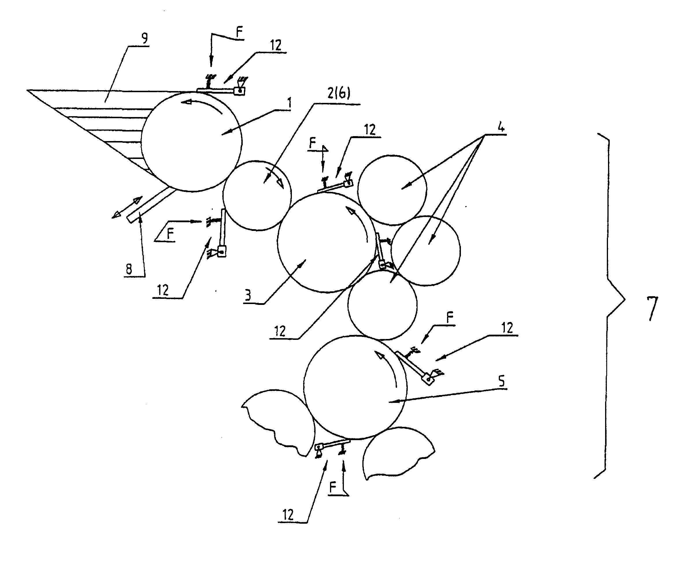
[0024] FIG. 1, the arrangement of a metering system for inking an inking unit,

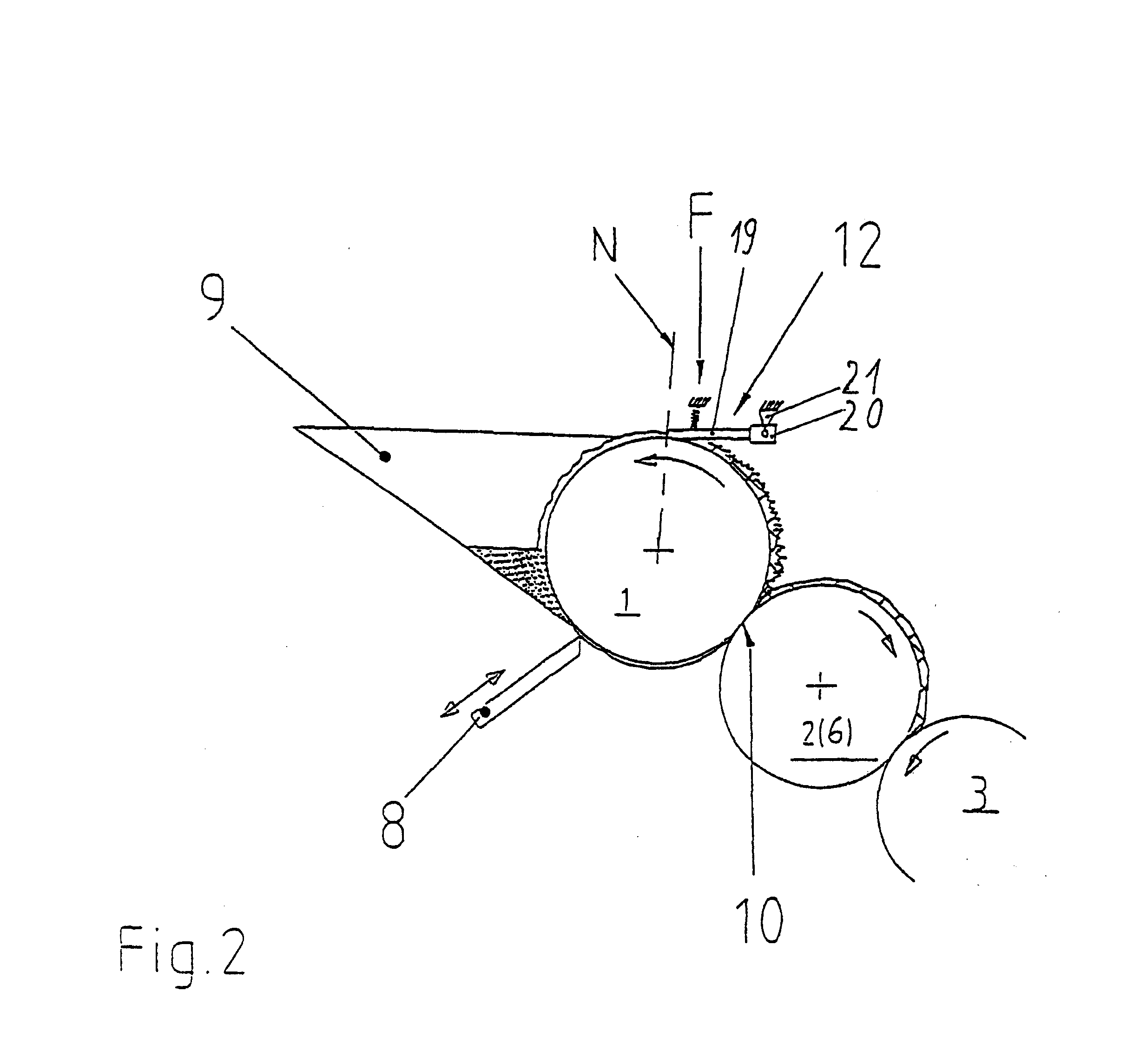
[0025] FIG. 2, an ink metering system in functional connection with an ink fountain roller,

[0026] FIG. 3, a metering system with an ink fountain roller and an ink dispensing device,

[0027] FIGS. 4a, b, representations of surface structures.

[0028] The offset printing press of a sheet-fed rotational printing machine essentially consists of an inking unit with an ink fountain roller 1 in functional connection with an ink fountain 9 with an ink metering system 8, e.g., ink valves, furthermore a vibrating roller 2 or a film roller 6 and an inking unit roller 3 configured as a first ink friction roller (can be driven with rotating and transverse axial motion) of a subsequent roller train 7. This roller train 7 leads to the plate cylinder (or form cylinder) and has, in a known way, a plurality of rollers, of wh...


PUM


Abstract

The invention concerns a metering system for the inking of rollers in a printing machine. The task of the invention is based on creating a metering system that achieves, with minimum expense, a uniform, stable ink guidance on a roller surface and noticeably improves the print quality. The task is solved in that, in the direction of rotation of a roller <bold>1, </highlight>preferably after a contact zone <bold>10, </highlight>where ink separation occurs, a plating device <bold>12 </highlight>is adjustable to the outer surface of the roller <bold>1. </highlight>

Description

DESCRIPTION[0001] The invention concerns a metering system for the inking of rollers in a printing machine, with at least one roller train leading to a plate or form cylinder, wherein the rollers can be inked by means of ink or lacquer from a storage container, according to the preamble of the main claim. The invention can preferably be used in an inking unit of a printing machine with a rotating roller arranged between an ink fountain roller and a subsequent inking unit roller, particularly in a film or vibrating inking unit.STATE OF THE ART[0002] A printing machine with a vibrating inking unit is known from DE 37 06 602 A1. Here, an ink fountain roller is in functional connection with an ink fountain with a metering system for the printing ink, as is known from, e.g., DE 27 11 553 A1. For printing machines with a vibrating inking unit, the printing ink is periodically removed in strips from an ink fountain roller by back and forth pendulate motion of an ink vibrating roller and fe...

Claims


Application Information

Patent Timeline
IPC IPC(8): B41F31/00B41F31/04B41F31/10
CPCB41F31/04B41F31/00
Inventor ZSCHETZSCHE, HUBERTHUMMEL, PETERORTNER, ROBERT
Owner MANROLANAD AG
Why Eureka
Try Eureka