Wick injection of liquids for colloidal propulsion

a technology of colloidal propulsion and liquid injection, which is applied in the direction of marine propulsion, machine/engine, vessel construction, etc., can solve the problem of water being lost from the wick by evaporation

Inactive Publication Date: 2003-11-13
FENN JOHN BENNETT
View PDF10 Cites 48 Cited by
  • Summary
  • Abstract
  • Description
  • Claims
  • Application Information

AI Technical Summary

Problems solved by technology

If the surrounding gas is not saturated with water vapor then water will be lost from the wick by evaporation.

Method used


Image

  • Wick injection of liquids for colloidal propulsion
  • Wick injection of liquids for colloidal propulsion
  • Wick injection of liquids for colloidal propulsion

Examples


Embodiment Construction

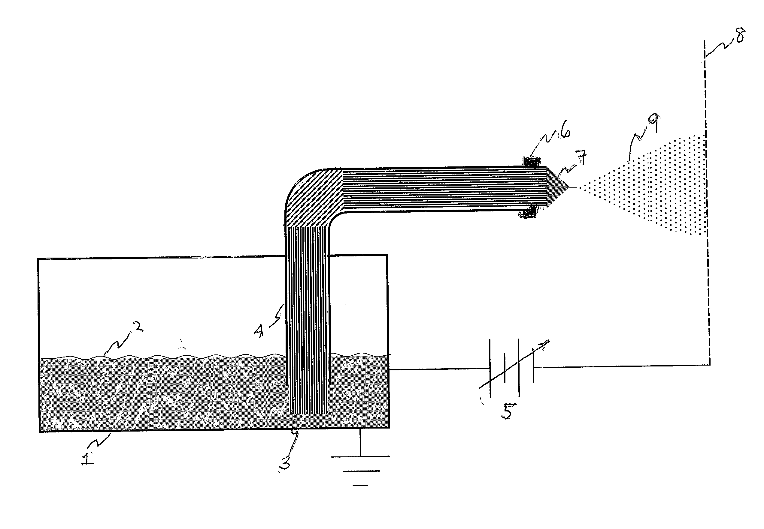
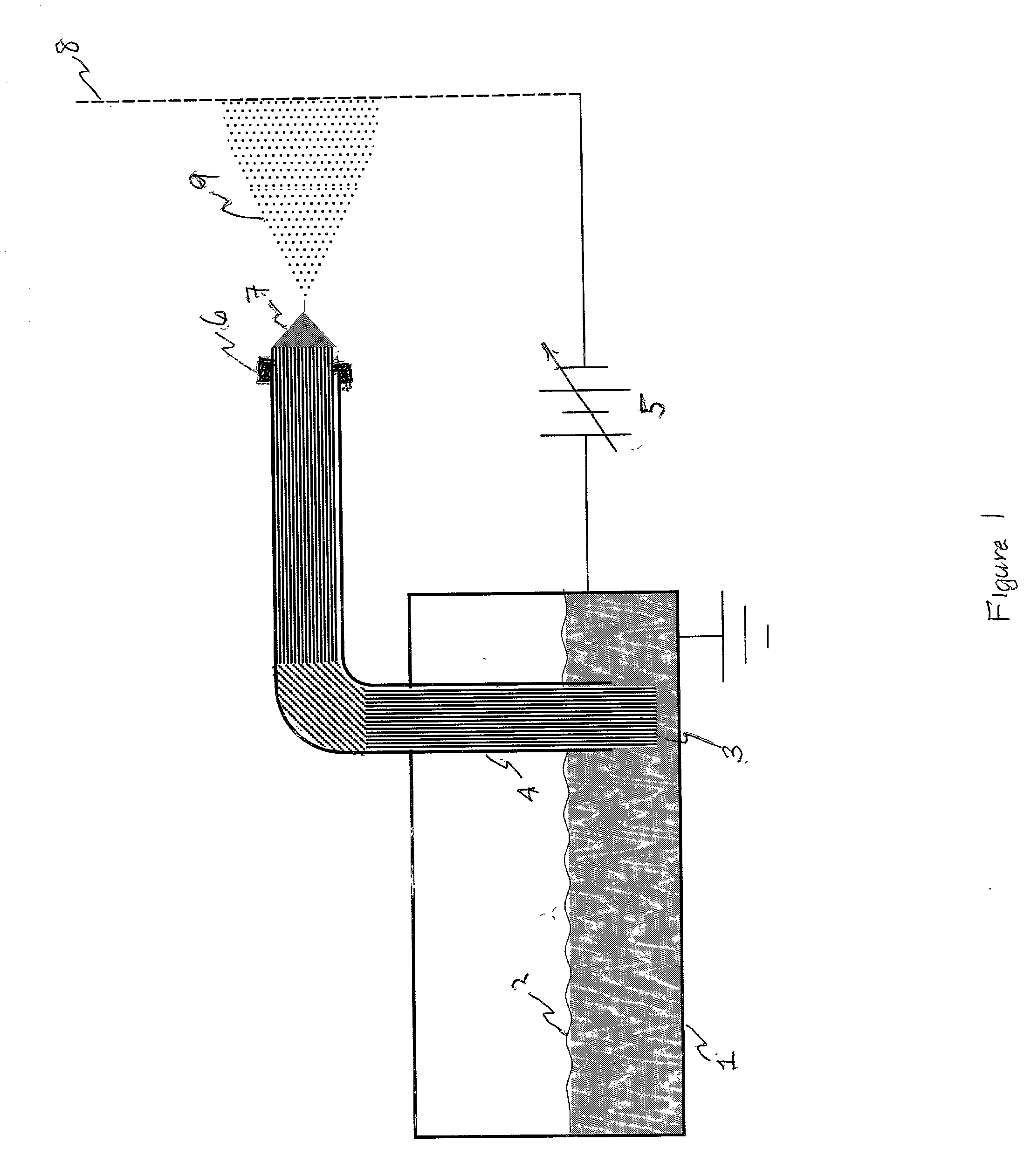
[0012] We have found that very stable electrosprays are readily produced when capillarity driven flow through a wick structure introduces a relatively nonvolatile conducting liquid into a high field region at very low pressure or in vacuum. FIG. 1 shows schematically the essential features of an arrangement by which such an electrospray is readily produced. Grounded reservoir 1 contains a supply of propellant liquid 2 having a low volatility. Wick 3, of a porous material wettable by liquid 2, extends from immersion in liquid 2 through conduit 4, terminating at or near its exit plane. It may sometimes be desirble to let the wick extend for a short distance beyond that exit plane. A seal 7 placed at the exit end of the tube limits leakage of liquid by flow around the wick. Such a seal may comprise a drop of cement that is allowed to set while the wick is dry and before liquid is added to reservoir 1. The cement should be such that it is not soluble in liquid 2 after it has set. Altern...


PUM


Abstract

Propellant liquid is supplied to a Colloidal Thruster for Micro-Satellite vehicles in Space by capillarity induced flow through a wick element comprising a permeable porous aggregate of fibers or particles of material that is wetted by the propellant liquid. An intense electric field at the tip of the wick element dispersed the arriving liquid into a fine spray of charged droplets. Electrodes having appropriate design, location and potentials accelerate the charge droplets to high velocity, thereby providing reactive thrust to the vehicle. In this method of propellant liquid introduction the flow rate and exhaust velocity, and therefore the thrust level, are determined by the applied potential difference, thereby eliminating the need for pumps or pressurized gas and flow controllers to provide the desired flow-rate for the propellant liquid.

Description

I. BACKGROUND[0001] For a variety of reasons there has recently been a growing interest in the possibilities of using very small satellites and probes for some space missions. This interest in "miniaturization" has stimulated a renewal of research in so-called "colloidal propulsion", the production of thrust by electrostatic acceleration of highly charged droplets or particles of nonvolatile liquids. Such use of charged droplets as propellants has its roots in studies carried out during World War I by John Zeleny, a physicist at Yale. He found that if a small-bore thin-walled tube was maintained at a high electrostatic potential relative to its surroundings or an opposing electrode, the electric field at the tube tip could be sufficiently intense to disperse an emerging conducting liquid into the ambient gas (air) as a fine spray of charged droplets [1]. (These tubes are frequently referred to as "spray needles" because they often comprise a short length of the stainless steel tubin...

Claims


Application Information

Patent Timeline
Patent Type & Authority Applications(United States)
IPC IPC(8): B05B5/025B64G1/40F02K9/44F02K99/00F03H1/00F03H99/00
CPCB05B5/0255B64G1/402F03H1/0012F02K9/44B64G1/405
Inventor FENN, JOHN BENNETT
Owner FENN JOHN BENNETT
Why Eureka
Try Eureka