
Method and apparatus for evaluating anisotropic materials

a technology of anisotropic materials and methods, applied in the direction of resistance/reactance/impedence, measurement devices, instruments, etc., can solve the problems of microwave system self-calibration and insensitivity, and not well suited to on-line industrial measurements

Inactive Publication Date: 2003-12-04
USNRKOCKUMS CANCAR
View PDF2 Cites 12 Cited by
  • Summary
  • Abstract
  • Description
  • Claims
  • Application Information

AI Technical Summary

Problems solved by technology

A limitation of the measurement method is that it only indicates the size of the grain angle, but not its sign.
It is not well suited to on-line industrial measurements.
This method is also designed for laboratory measurements with individual samples, and is not well suited to on-line industrial measurements,
This procedure makes the microwave system self-calibrating and insensitive to variations in the gain and phase shifts of the various microwave components involved.

Method used


Image

  • Method and apparatus for evaluating anisotropic materials
  • Method and apparatus for evaluating anisotropic materials
  • Method and apparatus for evaluating anisotropic materials

Examples


Embodiment Construction

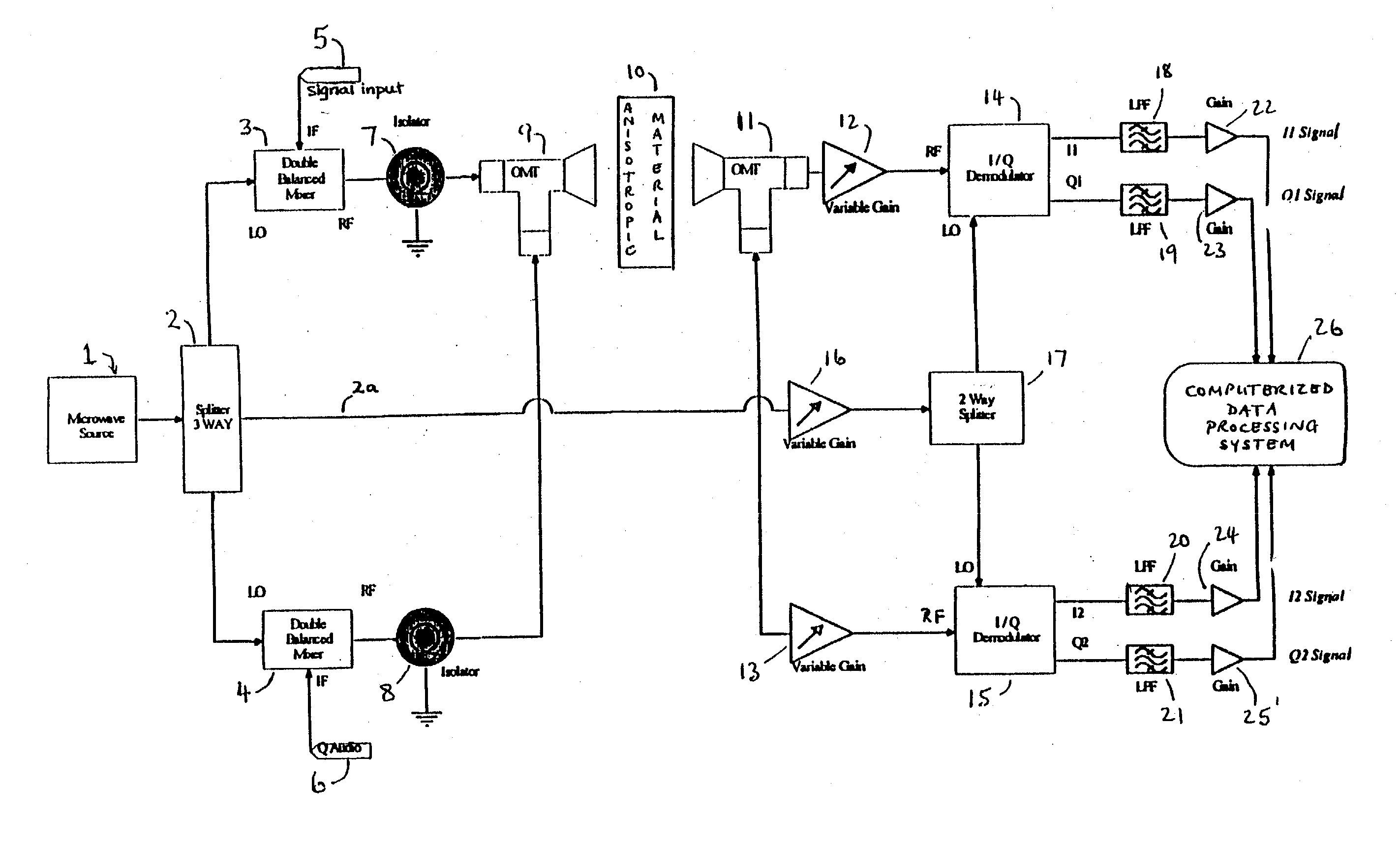
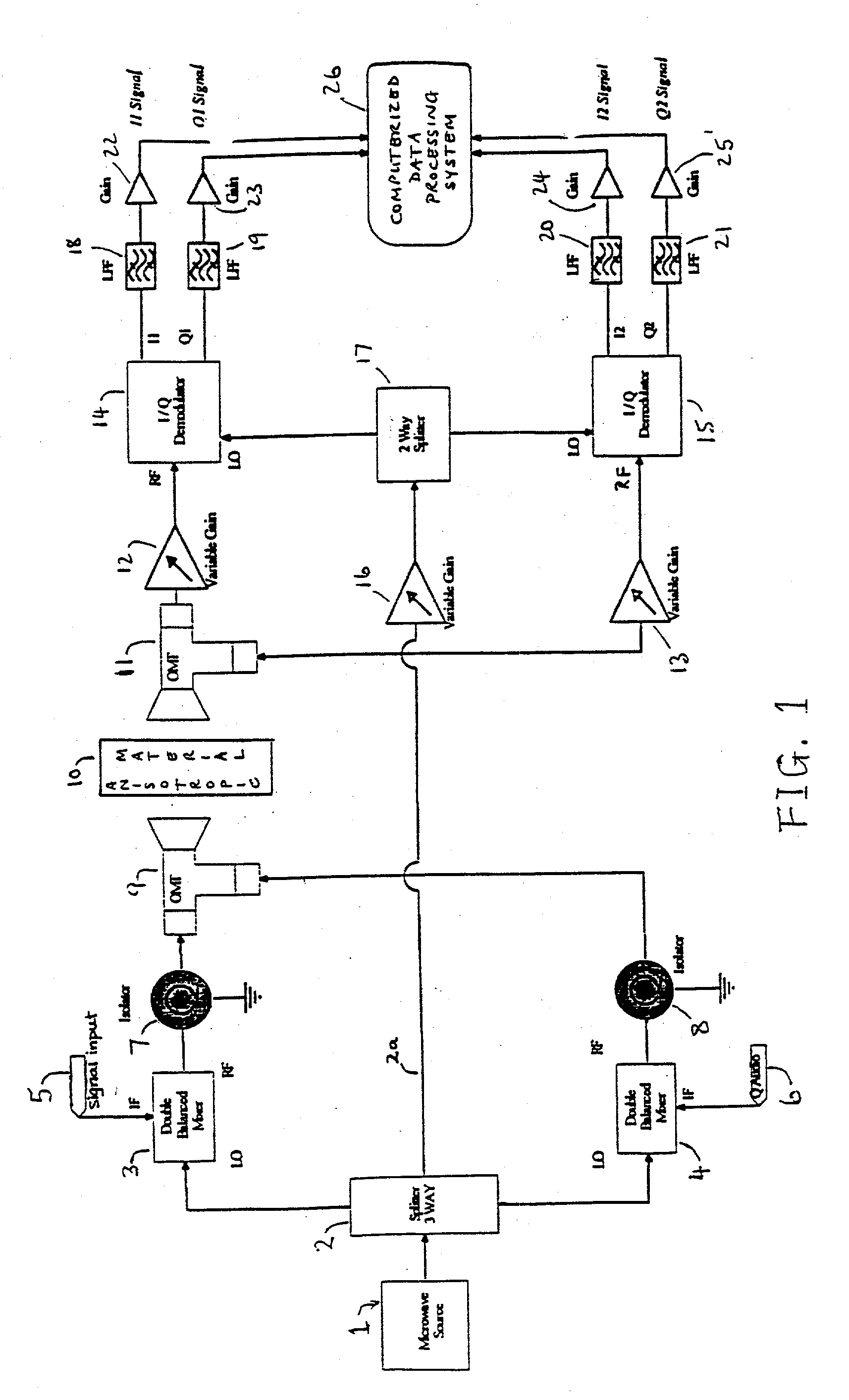
[0026] FIG. 1 shows a schematic diagram of one exemplary embodiment of the invention. A microwave source 1 is connected to a three-way splitter 2. Two branches of the splitter connect to double balanced mixers, 3 and 4, which are modulated by audio frequency signals 5 and 6. The outputs from the double balanced mixers pass through isolators 7 and 8 to an orthomode transducer 9. The orthomode transducer transmits a microwave beam towards and through the wood sample 10. This beam comprises the two signal components with mutually orthogonal planes of polarization. In general, this beam is elliptically polarized. There is no need, nor any effort made, to synchronize the phases of the two orthogonal components. That is, the present invention does not incorporate, nor require a rotator. Were the phases synchronized, then there would be, in effect, a rotating of the beam.

[0027] A second orthomode transducer 11 at the other side of the wood receives the orthogonal components of the microwav...


PUM


Abstract

An apparatus for evaluating dialectically-anisotropic materials comprising a plurality of microwave transmitters with differing planes of polarization, and a plurality of microwave receivers with differing planes of polarization, wherein each transmitter includes a means of modulating the microwave beam to be transmitted, the transmitters and receivers arranged, relative to a workpiece to be measured, so as to cooperate in communication therebetween, and wherein connected to each receiver is a processor to identify the received amplitude and phase of a component of the transmitted microwave beam, and to analyze by Fourier analysis the received signals to identify the principal axes, attenuations and phase shifts of the received microwave beam without requiring the phases of the transmitted microwave beams to be synchronized.

Description

[0001] The invention described here is an apparatus for evaluating the physical properties of anisotropic materials. It was originally conceived as an industrial device for sorting lumber, and therefore the descriptions given below are presented in that context. However, it can be seen that the invention can be successfully applied in much more general contexts. Therefore, the descriptions below should be understood to exemplify just one of a wide range of potential uses.[0002] When using wood for industrial purposes, it is important to exercise careful quality control to ensure that the material properties are properly matched to the desired end uses. However, wood is a natural material, and can have a wide range of mechanical properties, even within a single species. Consequently, it is important to be able to sort the wood into different grades, each with specific material properties. Such sorting allows the wood resource to be used efficiently and economically.[0003] Typical woo...

Claims


Application Information

Patent Timeline
IPC IPC(8): G01N22/00
CPCG01N22/00
Inventor SCHAJER, GARY S.
Owner USNRKOCKUMS CANCAR
Learn More