Field-flow fractionation method and apparatus

a field-flow fractionation and apparatus technology, applied in the direction of component separation, water/sludge/sewage treatment, material testing goods, etc., can solve the problems of reducing separation resolution, not the only possible application of field-flow fractionation, and reducing the resolution of separation, so as to reduce the use, simplify the general construction of the separation channel, and limit the presence of foreign elements

Inactive Publication Date: 2004-01-01
POSTNOVA ANALYTICS
View PDF7 Cites 68 Cited by
  • Summary
  • Abstract
  • Description
  • Claims
  • Application Information

AI Technical Summary

Benefits of technology

0041] It is desirable to simplify the general construction of the FFF separation channel. A channel design which minimizes the use of foreign elements such as splitters or frits is desirable so that a wide range of carrier solutions and samples are chemically compatible with the channel materials in co...

Problems solved by technology

Whereas sample species separation according to mass or size is often the goal of field-flow fractionation, this is not the only possible application of field-flow fractionation.
Band broadening is detrimental as it reduces the resolution of separation.
In current practice, the volume of the sample plug is limited by band broadening effects.
The disadvantage of this method is that the channel flow must be turned on and off; this typically requires an additional switching valve and extra time for equilibration.
The pressure transient generation is a most detrimental effect because the detectors used with FFF systems are sensitive to pressure transients.
As a consequence of the pressure transient, the detector signal is distorted from its normal baseline value and a significant amount of time may be required for the detector to return to baseline.
Whenever the detector response is disturbed, the separation cannot be accurately monitored, especially for species that elute at the beginning of the separation stage.
Additionally, the pressure transient may broaden or otherwise disturb the sample zone which is precisely positioned in its equilibrium distribution during the previous stop-flow period.
Either of these reasons will cause poor separation resolution.
In addition to these undesired pressure pulses, a stop-flow process may also lead to another undesirable effect, which is adhesion of sample species at the accumulation wall.
Second, engineering the pinched inlet presents severe difficulties because high performance FFF channels are already very thin, typically 100-200 micrometers.
Because of this small dimension, reducing the channel thickness near the inlet is very difficult and can hardly be done with sufficient precision.
Manufacturing a channel with an even channel thickness of just a few micrometers in the pinched inlet area is difficult.
Fourth, at high channel flow rates, eddy currents may be generated at the interface between the pinched inlet area and the full channel thickness.
Such eddy currents are undesirable because they may disturb the distribution of sample next to the accumulation wall.
Finally, the reduced thickness of the channel at the inlet is susceptible to clogging.
Nevertheless, this method has some disadvantages.
For use of a frit element for hydrodynamic relaxation, other disadvantages stem from the nature of frits.
Also, the particles which are gradually shed from frits interfere with the signal of light scattering detectors and elemental detectors which are commonly used in conjunction with FFF and other analytical separations.
Another disadvantage of the use of frits is the non-uniform flow throug...

Method used


Image

  • Field-flow fractionation method and apparatus
  • Field-flow fractionation method and apparatus
  • Field-flow fractionation method and apparatus

Examples


Embodiment Construction

[0160] The implementation of the liquid introduction and removal splitting devices should be relatively simple as illustrated in FIG. 8. For channels having a flat, planar structure in which plates are used to form the top and bottom channel walls, an additional layer of a spacer and a plate can be attached to the top channel plate. FIG. 8 illustrates the construction of an asymmetrical flow FFF channel which is modified to include a liquid introduction device. Modification of typical symmetrical flow FFF, thermal FFF, and electrical FFF channels would involve similar construction methods.

[0161] A channel cavity 14 is formed by using a channel spacer 64 consisting of a 0.025 cm thick film of Mylar with the channel shape cut out of it. The channel shape is tapered with triangular end pieces. The apex of each triangular end piece is co-linear with the center line of the channel. The initial and final breadth dimensions of channel 14 are 20 mm and 1 mm, respectively. The channel length...


PUM


Abstract

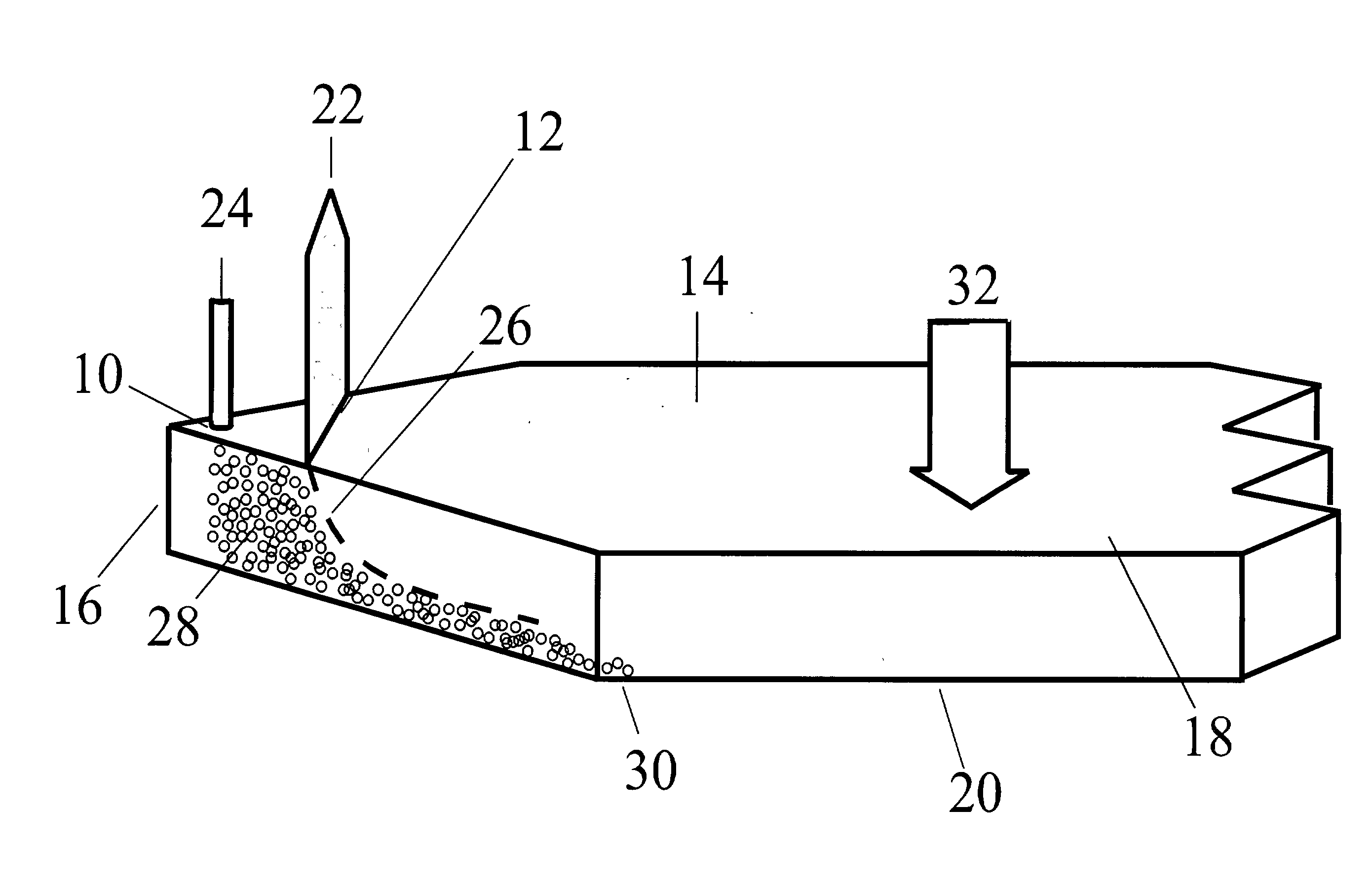
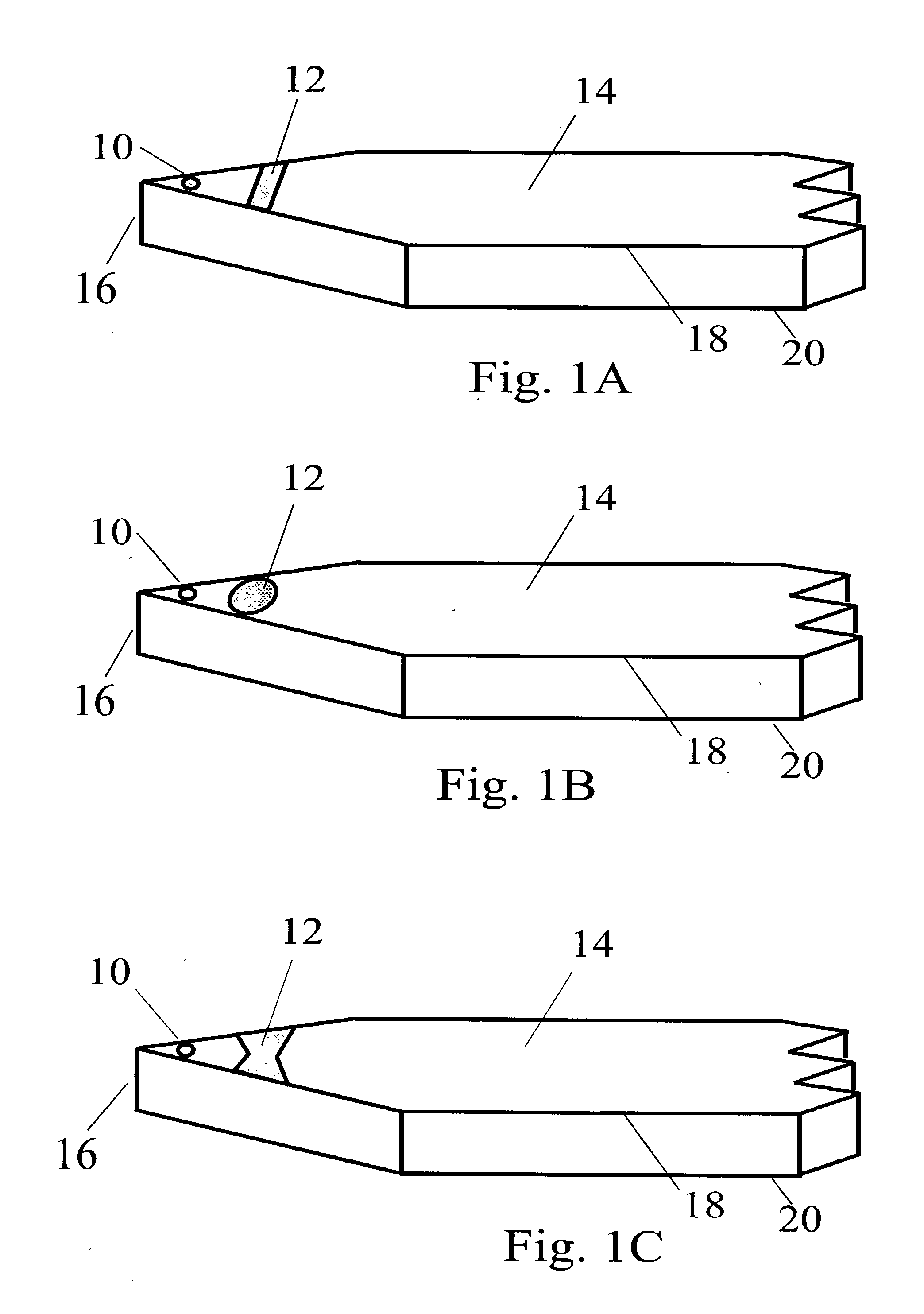
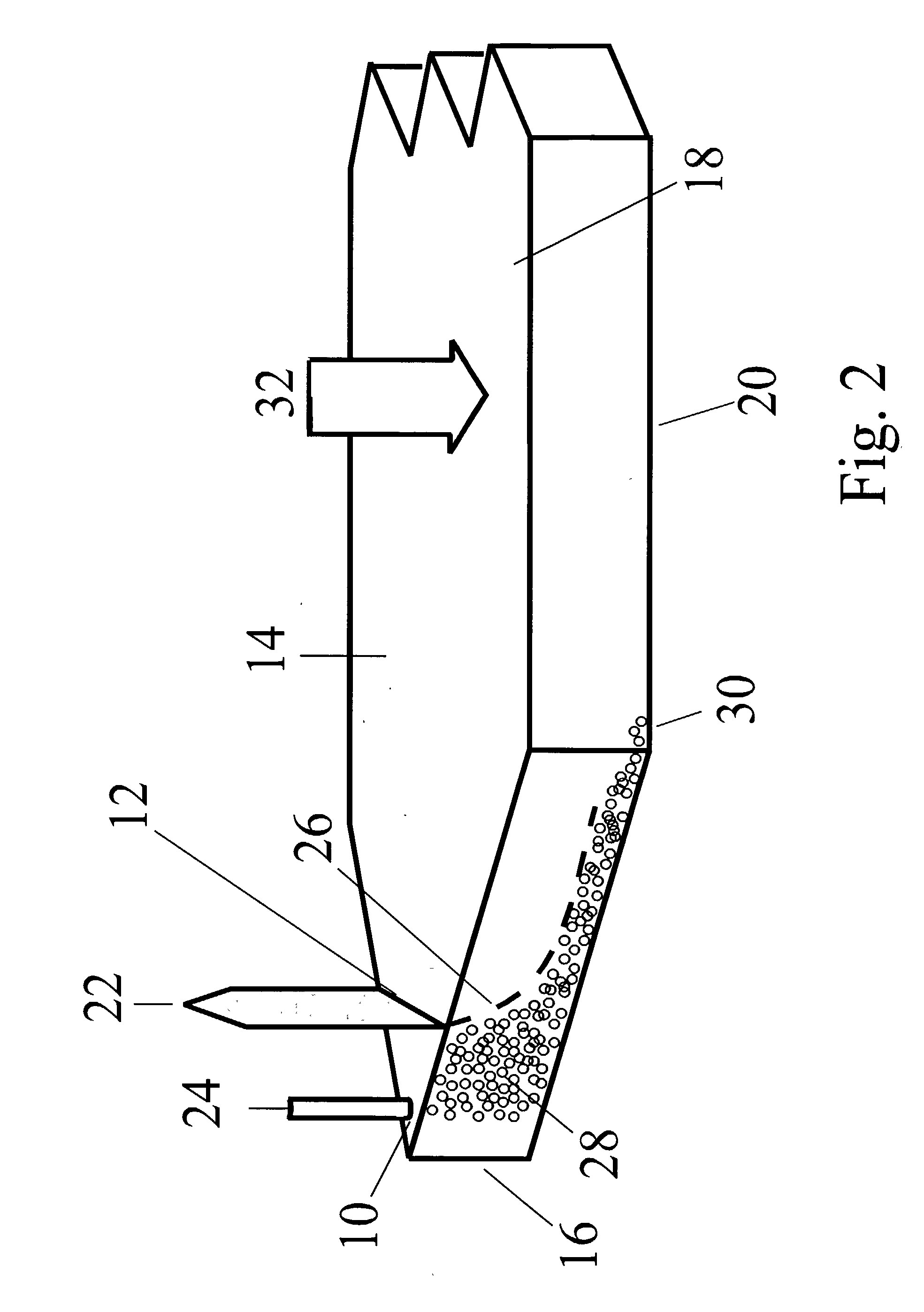
An improved field-flow fractionation method and apparatus for the separation of sample species 28 contained in a carrier fluid, wherein a stream of the sample species-containing carrier fluid is forced through a flow channel 14 having a depletion wall 18, an accumulation wall 20, side walls, a channel inlet 10, and a channel outlet 34, by introducing the sample species-containing carrier fluid into the flow channel 14 through the channel inlet 10 and withdrawing the sample species-containing carrier fluid through the channel outlet 34, a field 32 is applied to the carrier fluid in the flow channel 14 to induce a driving force on the sample species 28 acting across the flow channel 14 from the depletion wall 18 towards the accumulation wall 20 and perpendicular to the orientation of the main axis of the flow channel 14, the sample species 28 are subjected to fractionation as they flow through the flow channel 14 and emerge as sample species fractions at the channel outlet 34, wherein at least one additional stream of sample species-depleted carrier fluid is introduced into the flow channel 14 through at least one orifice 12 and the relative flow rates of the different streams are adjusted such that the stream of sample species-containing carrier fluid is positioned adjacent to the accumulation wall 20 and the sample species-depleted carrier fluid is positioned between the depletion wall 18 and the sample species-containing carrier fluid, no mechanical barrier being provided inside the flow channel 14 between the orifice 12 and the channel inlet 10 for separating the stream of sample species-depleted carrier fluid introduced through the orifice 12 and the stream of sample species-containing carrier fluid introduced through the channel inlet 10.

Description

1. THE FIELD OF THE INVENTION[0001] This invention relates generally to analytical separation techniques such as field-flow fractionation. More specifically, the present invention relates to a method and a device for splitting and / or combining two or more sample and liquid flows into or out of an analytical separation apparatuses, and in particular into or out of a field-flow fractionation separation system or channel.2. PRESENT STATE OF THE ART[0002] 2.1 Description of Field-Flow Fractionation, FFF[0003] Field-flow fractionation is a separation and characterization technique that relies on the effects of an applied field on a sample that is carried by a fluid flow. This fluid flow moves down the length of a channel that will hereinafter be referred to by the term "channel flow".[0004] The character and strength of the interaction between the species in the sample and the field plays a decisive role in the separation. Species that more weakly interact with the field are more rapidly...

Claims


Application Information

Patent Timeline
IPC IPC(8): G01N30/00
CPCG01N30/0005Y10T436/2575G01N30/6065G01N30/16
Inventor JIANG, YONGMILLER, MICHAEL E.MYERS, MARCUS N.KUMMEROW, ANDREAS M.TADJIKI, SOHEYLHANSEN, MARCIA E.KLEIN, THORSTEN
Owner POSTNOVA ANALYTICS
Why Eureka
Try Eureka