Apparatus and method for radio frequency tracking and acquisition

a technology applied in the field of antenna and receiver, can solve the problems of performance loss, increased acquisition time, and degraded performance of rf receiver

Inactive Publication Date: 2004-01-08
QUALCOMM INC
View PDF8 Cites 12 Cited by
  • Summary
  • Abstract
  • Description
  • Claims
  • Application Information

AI Technical Summary

Problems solved by technology

In certain channel conditions, the variation can deviate significantly from the designed operating point, resulting in a performance loss, such as increased acquisition time, smaller pu

Method used


Image

  • Apparatus and method for radio frequency tracking and acquisition
  • Apparatus and method for radio frequency tracking and acquisition
  • Apparatus and method for radio frequency tracking and acquisition

Examples


Embodiment Construction

[0015] Synchronization is an essential but challenging task performed in communication receivers. For a receiver to reliability demodulate the transmitted symbols, accurate knowledge of the symbol timing (i.e., when a symbol starts and ends) and carrier frequency is necessary. In addition, coherent receivers must be able to generate a reference signal whose phase is synchronous with that of the received radio frequency (RF) signal.

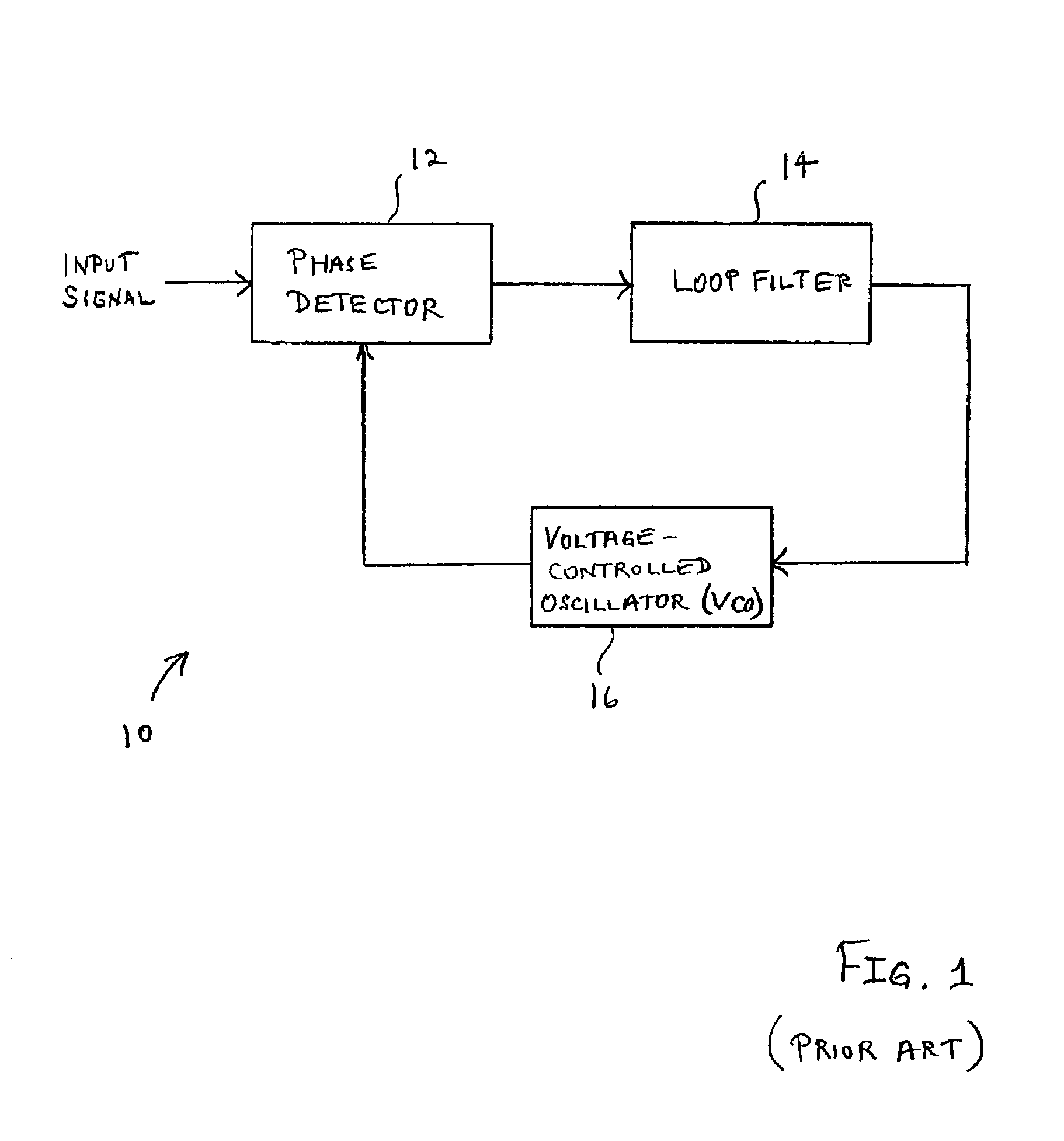
[0016] The most common synchronization technique is a phase-locked loop (PLL), which is used for both carrier phase and carrier frequency recovery. A time-tracking loop (TTL) is used for timing recovery. FIG. 1 illustrates a conventional PLL 10. As illustrated in FIG. 1, the PLL 10 is basically a feedback control system comprising three basic components: a phase detector 12, a loop filter 14, and a voltage-controlled oscillator (VCO) 16. Those skilled in the art will appreciate that the term VCO is typically used in analog circuits literature while the ter...


PUM


Abstract

A system and method for adjusting loop bandwidth in a synchronization loop of a radio receiver uses a noncoherent peak detector to determine the maximum magnitude and timing of incoming data at various code phase offsets. The maximum magnitude and timing are used in subsequent processing with the maximum magnitude value used to determine an adjustment factor. The timing information associated with the maximum signal value is used to despread the incoming signal. The despread incoming signal is subsequently scaled in accordance with the determined adjustment factor such that the input to the synchronization loop is scaled to produce the desired loop bandwidth.

Description

[0001] 1. Technical Field[0002] The present invention is related generally to radio frequency (RF) reception and, more specifically, to an apparatus and method for RF acquisition and tracking.[0003] 2. Description of Related Art[0004] Radio frequency (RF) receivers must be designed to acquire and track an incoming RF signal. In an ideal environment, the RF signal travels from a transmitter in a direct line to the receiver. However, in a more realistic setting, the RF signal from the transmitter is reflected or diffracted by various objects and arrives at the RF receiver along multiple pathways. In such a multipath environment, the signal power level fluctuates. In RF receivers synchronization loops , such as phase-locked loops, have a loop bandwidth designed for operation at a desired operating point. However, in a multipath environment, the loop bandwidth of the synchronization loop varies as the signal power level fluctuates. In certain channel conditions, the variation can deviat...

Claims


Application Information

Patent Timeline
IPC IPC(8): H04B1/16H04B1/00H04B1/707
CPCH04B1/7075
Inventor GLAZKO, SERGUEI A.LAI, KEUI-CHIANG
Owner QUALCOMM INC
Why Eureka
Try Eureka