Direct-injection spark-ignition engine

a spark ignition and direct injection technology, applied in the direction of machines/engines, liquid fuel feeders, mechanical apparatus, etc., can solve the problems of excessive fuel droplets, ignition failure, and apt fuel spraying toward the electrode of the spark plug, so as to accelerate evaporation and atomization of fuel, increase engine power, and reduce the amount of fuel droplets

Inactive Publication Date: 2004-01-22
MAZDA MOTOR CORP
View PDF6 Cites 17 Cited by
  • Summary
  • Abstract
  • Description
  • Claims
  • Application Information

AI Technical Summary

Benefits of technology

0010] This construction of the invention helps accelerate evaporation and atomization of the fuel as the fuel is injected through the multiple nozzle openings and dispersed in the form of fine particles. Since the central points of the fuel jets spewed out of the nozzle openings do not lie on the spark plug, it is possible to reduce the amount of fuel droplets adhering to the electrode and its surrounding areas. Furthermore, since the central points of the fuel jets, where the richest masses of fuel mists are present, are distributed around the electrode, slightly separated therefrom, it is possible to prevent formation of an excessively rich mixture at the electrode and properly regulate the air-fuel ratio around it to an ignitable level.
0011] The direct-injection spark-ignition engine thus constructed serves to achieve an increase in engine power, an improvement in fuel economy and a reduction in the amount of emissions.

Problems solved by technology

These prior art examples, however, have a problem that the fuel sprayed toward the electrode of the spark plug is apt to form droplets around the electrode and stick thereto.
The fuel droplets adhering to the electrode and its surrounding areas could cause an electric leakage resulting in an ignition failure.
Another problem of the prior art examples is that the mixture could become excessively rich around the electrode.

Method used


Image

  • Direct-injection spark-ignition engine
  • Direct-injection spark-ignition engine
  • Direct-injection spark-ignition engine

Examples


first embodiment

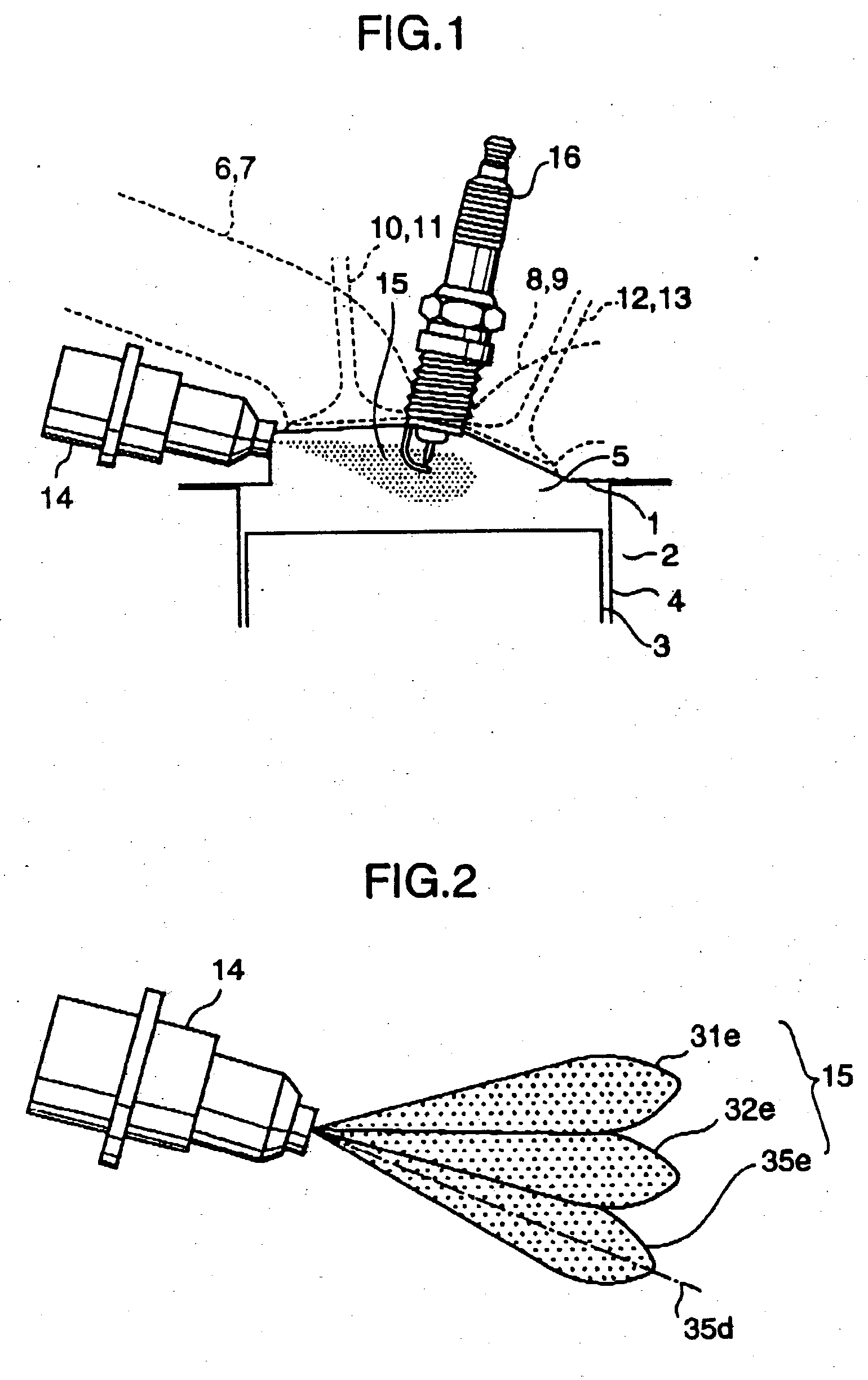
[0026] FIG. 1 is a fragmentary cross-sectional view of a direct-injection spark-ignition engine according a first embodiment of the invention, in which designated by the numeral 1 is a cylinder head mounted on top of a cylinder block 2, designated by the numeral 3 is a piston fitted in a cylinder bore 4 formed in the cylinder block 2, and designated by the numeral 5 is a combustion chamber formed between a top surface of the piston 3 and a bottom surface of the cylinder head 1. There is formed a cavity in the bottom surface of the cylinder head 1 to constitute a ceiling of the combustion chamber 5.

[0027] In this embodiment, two each intake ports 6, 7 and exhaust ports 8, 9 opening into the combustion chamber 5 in each cylinder are formed in the cylinder head 1. Intake valves 10 and 11 are provided in the intake ports 6 and 7 while exhaust valves 12 and 13 are provided in the exhaust ports 8 and 9, respectively. These intake valves 10, 11 and exhaust valves 12, 13 are actuated by uni...

second embodiment

[0042] FIG. 6A is a diagram showing the arrangement of openings 41-46 formed in a nozzle opening area 26 of an injector 14 according to a second embodiment of the invention, and FIG. 6B is a diagram showing how fuel jets spewed out of the individual openings 41-46 are distributed in an imaginary plane 90 immediately before ignition. As will be easily noticed, FIGS. 6A and 6B correspond to FIGS. 4 and 5 showing the first embodiment, respectively.

[0043] As depicted in FIG. 6A, there are formed six openings 41-46, which are also referred to collectively as openings 40, in the nozzle opening area 26 of the injector 14. The openings 41-43 are vertically arranged in the left half of the nozzle opening area 26, and the openings 44-46 are vertically arranged in the right half of the nozzle opening area 26. Axis lines of the openings 41-43 are inclined to the left in front view, while axis lines of the openings 44-46 are inclined to the right as shown by arrows in FIG. 6A. With the axis line...

third embodiment

[0047] FIG. 7A is a diagram showing the arrangement of openings 51-56 formed in a nozzle opening area 26 of an injector 14 according to a third embodiment of the invention, and FIG. 7B is a diagram showing how fuel jets spewed out of the individual openings 51-56 are distributed in an imaginary plane 90 immediately before ignition. As will be easily noticed, FIGS. 7A and 7B correspond to FIGS. 4 and 5 showing the first embodiment, respectively.

[0048] As depicted in FIG. 7A, there are formed six openings 51-56, which are also referred to collectively as openings 50, in the nozzle opening area 26 of the injector 14. The openings 51-56 are arranged on a vertical center line of the nozzle opening area 26. Axis lines of the openings 51, 53 and 55 are inclined to the right in front view, axis lines of the openings 52 and 54 are inclined to the left as shown by arrows in FIG. 7A, and an axis line of the opening 56 is not inclined either way. With the axis lines of the openings 50 arranged ...


PUM


Abstract

A direct-injection spark-ignition engine includes a spark plug provided approximately at the center of the ceiling of a combustion chamber, and an injector having at its downstream end a nozzle which is located in an upper peripheral area of the combustion chamber, in which multiple openings are formed in the nozzle of the injector. Fuel is injected from the nozzle of the injector directly toward the proximity of an electrode of the spark plug. The directions of axis lines of the individual openings are set such that central points of fuel jets spewed out of the individual openings do not lie on the spark plug but are distributed around the electrode, slightly separated therefrom.

Description

[0001] 1. Field of the Invention[0002] The present invention relates to a direct-injection spark-ignition engine in which an end of an injector is located inside a combustion chamber such that a mist of fuel sprayed from the injector is locally distributed in the proximity of an electrode of a spark plug.[0003] 2. Description of the Related Art[0004] There exists a conventionally known direct-injection spark-ignition engine which is provided with a spark plug and an injector for feeding fuel directly into a combustion chamber to achieve an improvement in fuel economy by stratified charge combustion. In this kind of engine, it is necessary to accelerate evaporation and atomization of the fuel while minimizing dispersion of the fuel and to maintain a condition under which an ignitable mixture of an appropriate air-fuel ratio is locally distributed around an electrode of the spark plug.[0005] Techniques for achieving such objectives are disclosed in Japanese Unexamined Patent Publicati...

Claims


Application Information

Patent Timeline
Patent Type & Authority Applications(United States)
IPC IPC(8): F02P13/00F02B17/00F02B23/10F02B75/12F02M45/02F02M61/14F02M61/18F02M69/04
CPCF02B17/005F02B23/105F02B2023/103F02B2075/125Y02T10/123F02M61/1806F02M69/045Y02T10/125F02M45/02Y02T10/12
Inventor YAMASHITA, HIROYUKIOHTA, NORIYUKISAITO, FUMIHIKOARAKI, KEIJI
Owner MAZDA MOTOR CORP
Why Eureka
Try Eureka