Device and system for dispensing or aspirating/dispensing liquid samples

a liquid sample and liquid technology, applied in liquid dispensing, combinational chemistry, chemical libraries, etc., can solve the problem of limiting the resolution of the quantity of liquid to be dispensed

Inactive Publication Date: 2004-02-05
TECAN TRADING AG
View PDF10 Cites 14 Cited by
  • Summary
  • Abstract
  • Description
  • Claims
  • Application Information

AI Technical Summary

Benefits of technology

0011] The present invention will now be explained in more detail by reference to schematic drawings...

Problems solved by technology

The size of the drop thus limits the resolution of the quantity of liquid to be dispensed.
As a result of the definition of the vo...

Method used


Image

  • Device and system for dispensing or aspirating/dispensing liquid samples
  • Device and system for dispensing or aspirating/dispensing liquid samples
  • Device and system for dispensing or aspirating/dispensing liquid samples

Examples


first embodiment

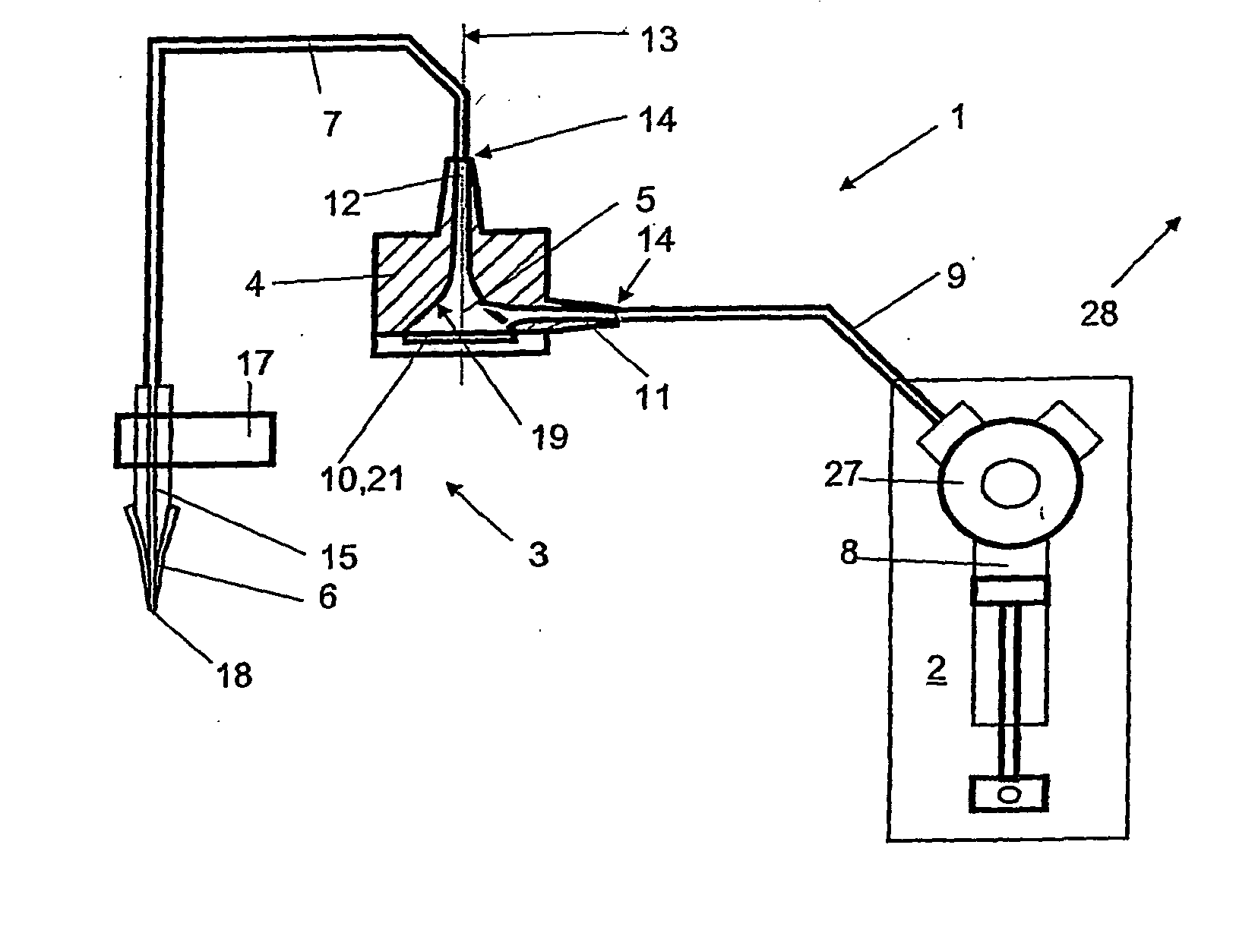
[0017] FIG. 1 shows a diagrammatic view of a device for dispensing or aspirating / dispensing liquid samples according to a Said device 1 comprises a pump 2 and a micro-ejection apparatus 3. The micro-ejection apparatus comprises an impulse generator 4 with a chamber 5 and is filled completely with a liquid which thus forms a continuous liquid column. The impulse generator 4 is arranged in such a way that, for the purpose of producing the dispensing of liquid samples, pressure waves can be produced in the liquid. The micro-ejection apparatus 3 further comprises an end piece 6 and a liquid tubing 7. The liquid tubing 7 has a length of approx. 1 m in an embodiment and connects the impulse generator 4 with the end piece 6. The inside diameter of said tubing 7 is 0.8 mm in this embodiment and the wall thickness measures 0.6 mm.

[0018] Preferably, the pump 2 is a reciprocating pump or a diluter of type "CAVRO XP 3000 plus Modular Digital Pump". The cylinder 8 of the diluter has a volume in...

second embodiment

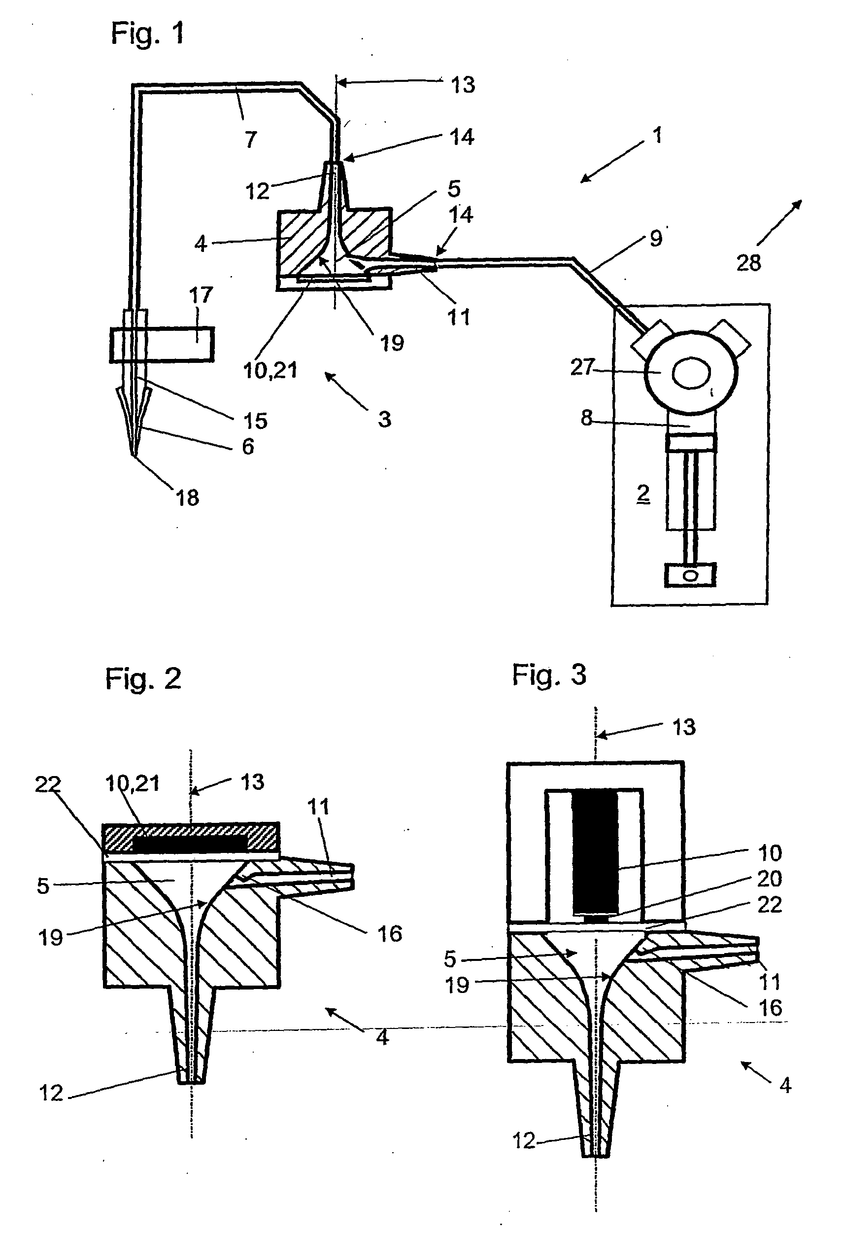
[0026] FIG. 3 shows a sectional view through an impulse generator 4 according to a The axis of symmetry 13 lies co-axially to the output channel 12. A micro-actuator 10 which operates on a magnetic basis is arranged at a right angle to the axis of symmetry 13. A membrane 22 for transmitting impulses onto the liquid in the chamber 5 is arranged between the actuator arranged as a solenoid 20 and the chamber 5. Said membrane 22 closes off the chamber 5 at the rear side. Instead of a solenoid working on a magnetic basis it would also be possible to use a stack of piezo-elements (not shown). The input channel 11 is provided at its transition point to the inner wall 19 of chamber 5 with a narrowed section 16.

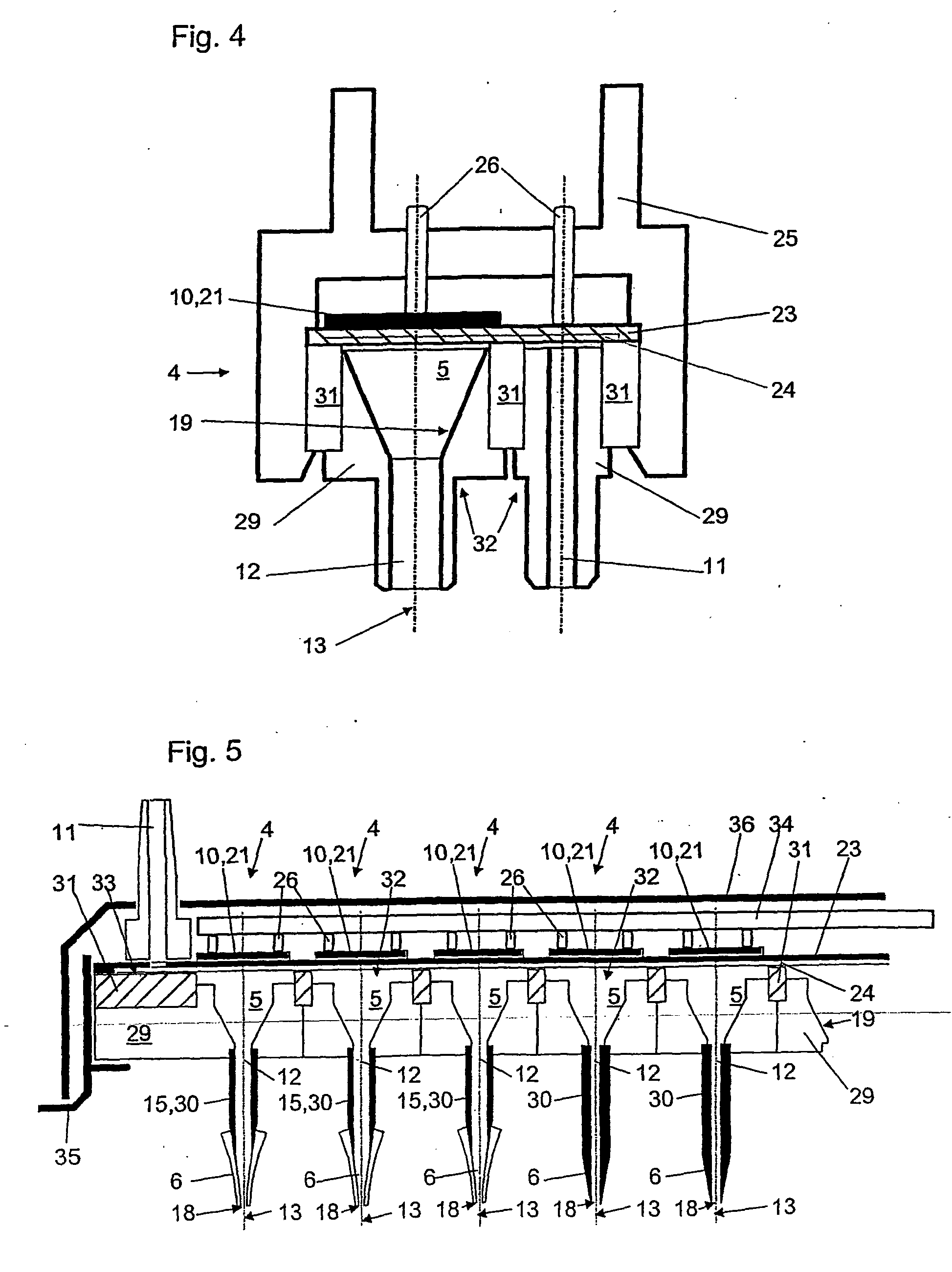
[0027] FIG. 4 shows a sectional view through an impulse generator 4 according to a third embodiment. The axis of symmetry 13 lies co-axially to the output channel 12. A piezo-element 21 is arranged as a micro-actuator 10 at a right angle to the axis of symmetry 13 and is glued onto a...

fourth embodiment

[0032] FIG. 5 shows a sectional view through an array of impulse generators according to a The individual chambers 5 of the adjacently arranged impulse generators 4 are arranged in a component 29 which consists of a polymer material which is integrally injection-molded or turned individually from solid material for example. Needles 30 are arranged co-axially with the axis of symmetry 13 of chambers 5 and form the output channel 12 of the same. Preferably, said needles 30 consist of stainless steel and taper to a point at their free end in such a way that they can either be used directly as end pieces 6 (i.e. as pipette tips) or they each can receive a disposable tip.

[0033] In a partial or even close contact with said component 29, a compartmenting structure 31 is sealingly connected with the component 29 on its upper side. Said compartmenting structure 31 preferably consists of a glass plate from which compartments 32 are arranged in such a way that they correspond in the register ...


PUM


Abstract

The invention relates to a device (1) for dispensing or aspirating/dispensing liquid samples, comprising a pump (2) and a micro-ejection device (3), said micro-ejection device (3) having a pulse generator (4) with a chamber (5). Said pulse generator (4) is used to produce pressure waves in the liquid in order to cause the samples of a liquid to be dispensed. The micro-ejection device (3) also comprises an end piece (6) and a liquid line (7) which connects the pulse generator (4) to the end piece (6). The pulse generator comprises a micro-actuator (10) which is configured to function in the same direction as that in which the pressure wave leaves the chamber (5). The inventive devices are characterised in that the chamber (5), in the area of the end facing away from the end piece (6), or the corresponding connecting element (14) has a narrowed section (16) which restricts any expansion of the pressure waves in the direction of the pump (2). The invention also relates to systems with multiple devices of this type.

Description

RELATED PATENT APPLICATIONS[0001] This application claims priority of the Swiss patent application No. 2252 / 00 filed on Nov. 17, 2000, the Swiss patent application No. 2314 / 00 filed on Nov. 29, 2000, the Swiss patent application No. 2413 / 00 filed on Dec. 12, 2000, and the international application PCT / CH01 / 00639 filed on Oct. 29, 2001.[0002] According to the preamble of the independent claim 1, the invention relates to a device for dispensing or aspirating / dispensing liquid samples, comprising a pump and a micro-ejection apparatus, with said micro-ejection apparatus having an impulse generator with a chamber and with said impulse generator being used to pressure waves in the liquid in order to cause the samples of a liquid to be dispensed, and with said micro-ejection apparatus further comprising an end piece and a liquid line which connects the impulse generator to the end piece and with the impulse generator comprising a micro-actuator which is configured to function in the same d...

Claims


Application Information

Patent Timeline
IPC IPC(8): B01J4/00B01J4/02B01L3/02B01L3/14B01L99/00C40B60/14G01F25/00G01N35/10
CPCB01J2219/00378B01L99/00B01L3/022B01L3/0268B01L3/5021B01L2400/025B01L2400/0439B01L2400/0478C40B60/14G01F25/0092G01N35/1016G01N35/1065G01N2035/1006G01N2035/103G01N2035/1034G01N2035/1039G01N2035/1041B01L3/021B01L13/02
Inventor INGENHOVEN, NIKOLAUSHODAC, AGATHESCHMID, NOA
Owner TECAN TRADING AG
Why Eureka
Try Eureka