Two piece oil control ring with nitrided surface layers

a technology of nitrided surface layer and oil control ring, which is applied in the direction of solid-state diffusion coating, machines/engines, brake systems, etc., can solve the problems of detrimentally increasing oil consumption, unable to uniformly lap the end portions deteriorating roundness or circularity of the ring body, so as to control or restrict deformation or warpage, control or suppress deformation

Inactive Publication Date: 2004-02-05
RIKEN CO LTD
View PDF7 Cites 7 Cited by
  • Summary
  • Abstract
  • Description
  • Claims
  • Application Information

AI Technical Summary

Benefits of technology

0016] FIG. 1 illustrates a ring boy 1 used in an oil control ring according to the present invention. Ring body 1 is formed of stainless steel containing chromium of 3.0 to 13.0 weight %, and is coated with nitrided layers 13 that comprises an outer nitrided layer 14 formed on an outer circumferential surface 11 of ring body 1; and an inner nitrided layer 15 formed on an inner circumferential surface 12. Similarly to prior art oil control ring shown in FIG. 6, ring body 1 of FIG. 1 is formed with a plurality of openings 8 through which lubricating oil passes. Ring body 1 has its width B: 1.2 to 2.0 mm, thickness t: 1.2 to 2.0 mm, land (rail) width l.sub.0: 0.15 to 0.22 mm and annular groove depth t.sub.0: 0.5 to 0.75.
0017] Nitridation expansion of ring body 1 generates different deformation of outer and inner nitrided layers 14 and 15, resulting in warpage of ring body 1, and it would be necessary to balance compressive forces resulted from nitridation expansion of outer and inner nitrided layers 14, 15 in order to control or restrict deformation or warpage of ring body 1.
0018] Assuming that .DELTA. F.sub.o and .DELTA. F.sub.i respectively indicate outer and inner circumferential forces generated in each small area .DELTA.A.sub.o and .DELTA.A.sub.i on an imaginary sectional line m-n in ring body 1, and L.sub.o and L.sub.i respectively represent distances from neutral stress axis N to central points of small area .DELTA.A.sub.o and .DELTA.A.sub.i, if total or integrated moments of force exerted on small areas .DELTA.A.sub.o and .DELTA.A.sub.i are substantially equal to each other, it can be appreciated that no deformation would occur in ring body 1, as shown by the following formula (1):
0019] In this case, distances L.sub.o and L.sub.i from neutral stress axis N to central points of small area .DELTA.A.sub.o and .DELTA.A.sub.i are not equal (L.sub.o.noteq.L.sub.i) to each other. Suppose k=.SIGMA.L.sub.o / .SIGMA.L.sub.i, equation (1) can be developed to equation (2):
0020] As forces resulted from expansion of nitrided layers are in proportion to areas of nitrided layers, if outer and inner nitrided small areas are shown by .DELTA.A.sub.o and .DELTA.A.sub.i, equation (2) can be developed to equation (3). Also, assuming that A.sub.o and A.sub.i represent total outer and inner nitrided areas respectively, equation (3) can be rewritten as equation (4). Moreover, supposing Y.sub.o and Y.sub.i indicate whole surface (edge) lengths of the outer and inner nitrided areas in cross section of ring body 1 with the nitrided layer of constant thickness t, we have: A.sub.o=Y.sub.o.times.t and A.sub.i=Y.sub.i.times.t-. If these equations are substituted for equation (4), we have equation (5).
0021] Accordingly, these equations show that ring body 1 should be formed with a constant ratio of outer surface (edge) length to inner surface (edge) length in section areas in order to control or suppress deformation due to nitridation.

Problems solved by technology

This oil control ring is, however, disadvantageous in that roundness or circularity of ring body is remarkably deteriorated with warpage upon nitriding expansion during and after a nitriding process because the process involves unbalanced stresses produced in inner and outer nitrided layers of ring body formed into M- or I-shape made of stainless steel having low chromium content.
When the lapping process is applied to circumferential surfaces of such deformed ring, the end portions of ring body cannot uniformly be lapped due to distortion by nitriding.
When an oil control ring of degraded circularity is attached to a piston, it provides a clearance or gap between an inner surface of a cylinder and outer circumferential surface of the oil ring, thereby resulting in detrimentally increased oil consumption.
Otherwise, when the whole outer circumferential surface is lapped to a required periphery circularity of ring body, the nitrided layer is disadvantageously removed by lapping, and therefore, after nitriding, lapping of the ring body is extremely restricted or should be performed very carefully.
However, cost problem is still involved in 17% Cr stainless steel.

Method used


Image

  • Two piece oil control ring with nitrided surface layers
  • Two piece oil control ring with nitrided surface layers
  • Two piece oil control ring with nitrided surface layers

Examples


Embodiment Construction

[0022] To test oil control rings according to the present invention, ring bodies of different cross section of nine (9) kinds were prepared and lapped with lapping agent untill lapped profile was formed on whole outer circumferential surfaces of each ring body, measuring lapping time therefor and checking status of lapped nitrided layers. Test results is shown in the following table wherein symbols show the following:

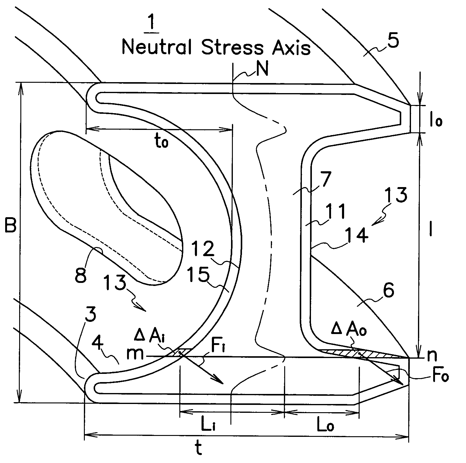
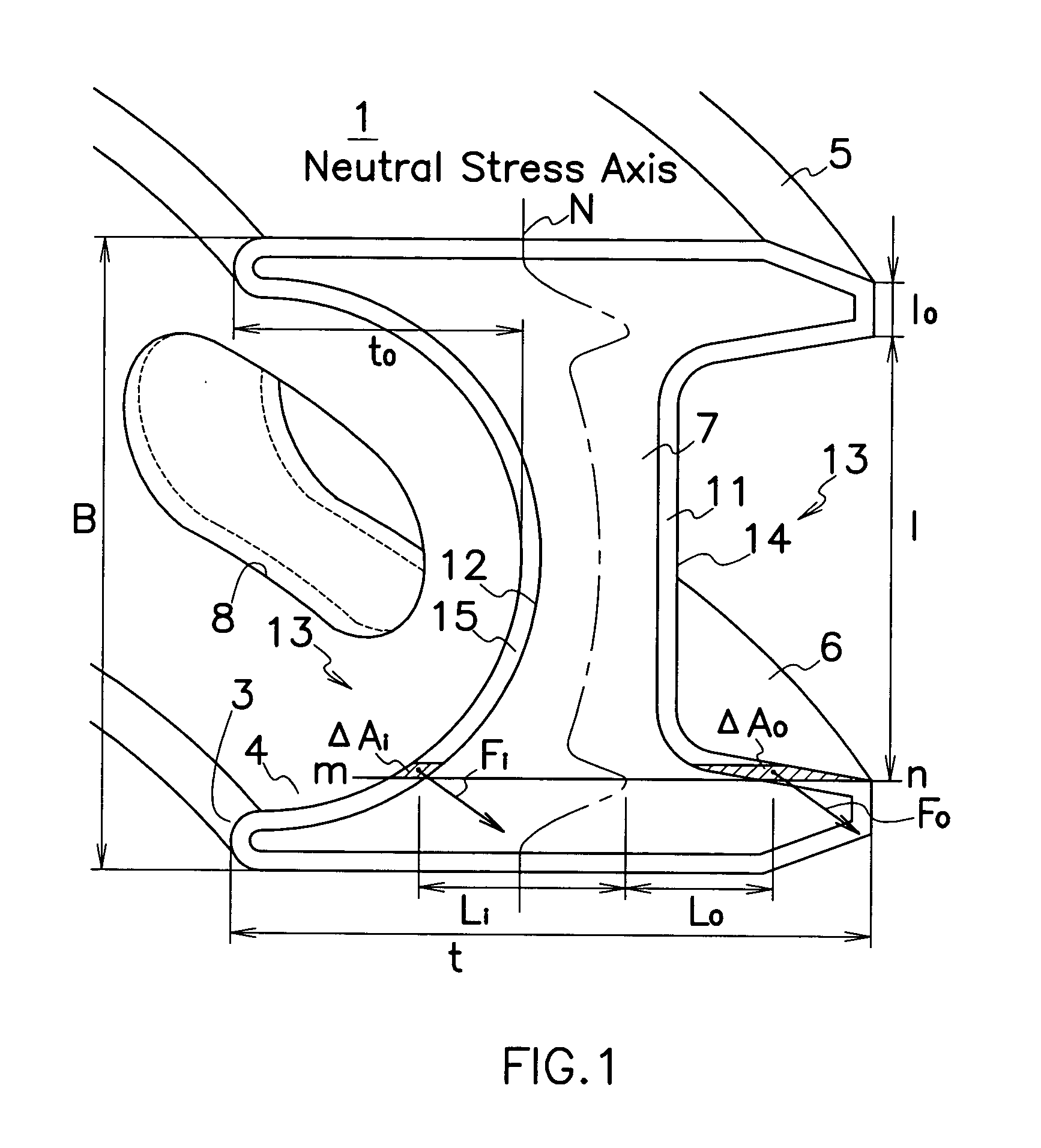
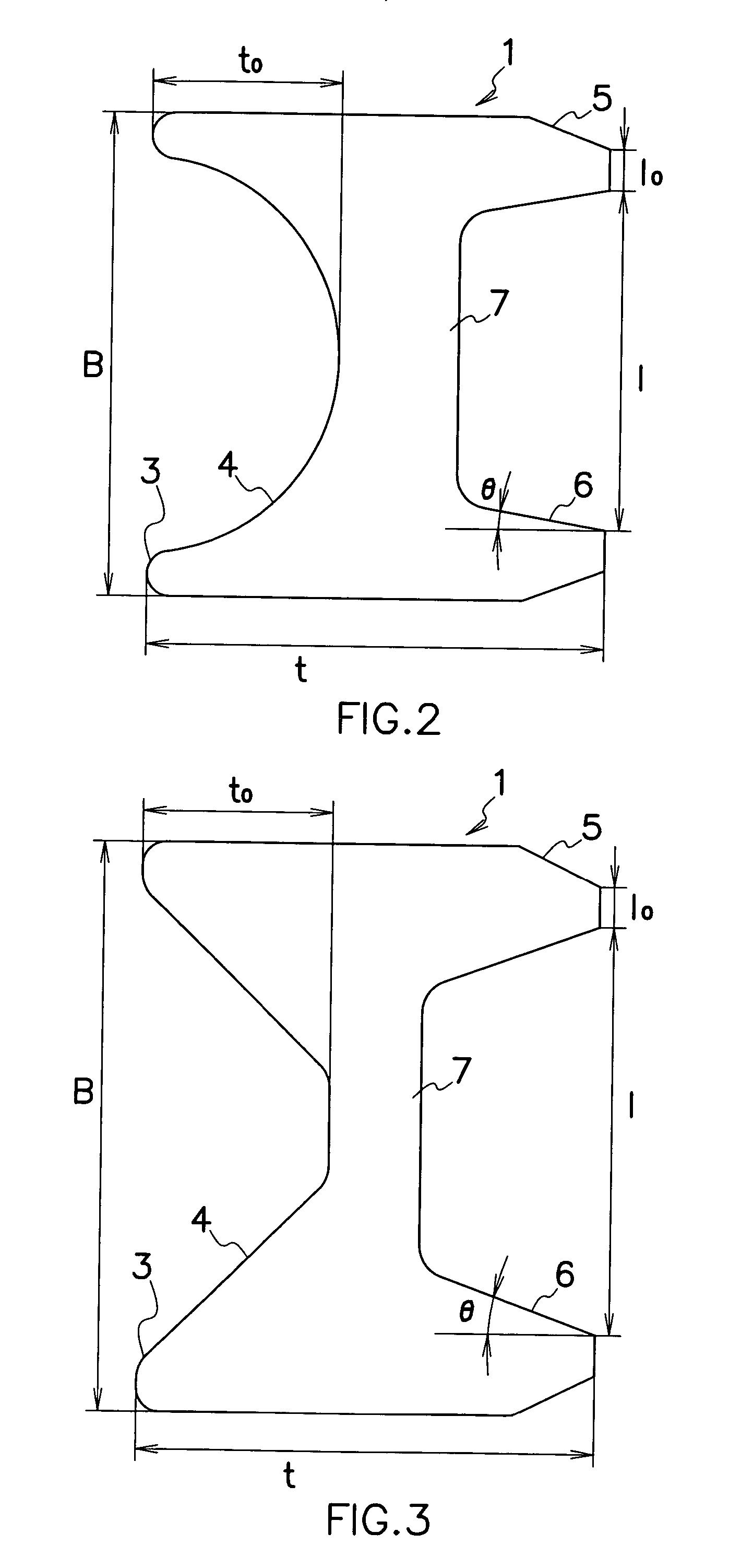
[0023] B(mm): Width of ring body; t (mm): Thickness of ring body; l.sub.0 (mm): Land (Rail) width; l (mm): Length between rails; t.sub.0 (mm): Groove depth; .theta. (degrees): Rail angle; .tau.: Circular ratio of an outer surface (edge) length Y.sub.o to an inner surface (edge) length Y.sub.i in cross section of ring body 1; T (seconds): Lapping time; A: Whole nitrided layers that do not survive lapping; P: Whole nitrided layers that survive lapping.

1TABLE Test Result Sample No. B t l.sub.0 l t.sub.0 .theta. .tau. T A / P 1 1.5 1.5 0.18 1.06 0.7 9 1.01 150 A 2 1.5 1.5 0.1...


PUM

PropertyMeasurementUnit
widthaaaaaaaaaa
thicknessaaaaaaaaaa
thicknessaaaaaaaaaa

Abstract

A two piece oil control ring is provided which comprises a ring body (1) formed into a generally M- or I-shaped section with an annular groove (4) on an inside surface (3) of the ring body (1); and a coiled expander (2) attached in the annular groove (4) of the ring body (1) for resiliently urging the ring body (1) toward an inner wall of a cylinder. The ring body (1) is made of stainless steel that contains chromium of 3.0 to 13.0 weight % with the outer and inner circumferential surfaces (11, 12) covered with nitrided layers (14, 15). Circular ratio (tau) of an outer edge length (Yo) to an inner edge length (Yi) in the cross section of the ring body (1) is in a range between 1.08 and 1.32 to keep precise peripheral circularity of the ring body so that the nitrided layers survive lapping of the ring body (14, 15).

Description

[0001] This invention relates to an oil control ring attached in a ring groove of a piston in an internal combustion engine, in particular to a two piece oil control ring that has a coiled expander and a ring body with nitrided surface layers formed thereon.[0002] Various types of coil expander loaded oil control rings have generally been utilized in most of diesel engines. A typical example of two piece oil control rings comprises, as shown in FIG. 6, a ring body 1 with an annular groove 4 on an inside surface 3 of ring body 1; and a coiled expander 2 attached in annular groove 4 of ring body 1. Ring body 1 comprises an upper rail 5, a lower rail 6 and a web 7 that connects upper and lower rails 5, 6 to form a generally M-shaped section. A plurality of openings 8 are formed in web 7 to allow lubricating oil to pass through the openings 8.[0003] Not shown but, wear resistant surface layers are formed on outer peripheral surfaces of upper and lower rails 5, 6, and on inner peripheral...

Claims


Application Information

Patent Timeline
Patent Type & Authority Applications(United States)
IPC IPC(8): F02F5/00C22C38/18C23C8/26F16J9/06F16J9/20F16J9/26
CPCC22C38/18F16J9/26F16J9/062C23C8/26F16J9/06
Inventor TAKIZAWA, AKIYOSIKATAYAMA, NOBUO
Owner RIKEN CO LTD
Why Eureka
Try Eureka