Switching power source

a power source and power supply technology, applied in the direction of electric variable regulation, process and machine control, instruments, etc., can solve the problems of power source giving, and increasing switching loss and conversion efficiency in dc-dc converters, so as to improve the conversion efficiency of power sources and reduce switching losses. , the effect of wide fluctuation range of power voltag

Inactive Publication Date: 2008-07-01
SANKEN ELECTRIC CO LTD
View PDF8 Cites 52 Cited by
  • Summary
  • Abstract
  • Description
  • Claims
  • Application Information

AI Technical Summary

Benefits of technology

[0008]Under the low input voltage (VDC) from the DC power supply (1), the switching element (3) is turned on at the time the bottom voltage detector (51) detects a first bottom point of the voltage (VDS) across the switching element (3). In other words, when voltage (VDS) across the switching element (3) comes to the bottom point after energy has been released from the transformer (2), pseudo resonance action is performed to turn the switching element (3) from the off to the on condition. Meanwhile, when the input voltage (VDC) from the DC power supply (1) so rises that detection voltage (VDT) of the voltage detector (31) is above the reference voltage (VR2), the switching controller (61) serves to late turn the switching element (3) on at the time the bottom voltage detector (51) detects the second or later bottom point of the voltage (VDS) across the switching element (3), extending the off period of the switching element (3) to reduce the switching frequency of the switching element (3). Accordingly, the power source enables decrease in switching loss by diminishing the switching number of the switching element (3) under the elevated input voltage to improve the conversion efficiency of the power source in a wide fluctuation range of the power voltage.
[0009]Accordingly, the switching power source can be applied to any of various worldwide power voltages with less switching loss. Moreover, the power source can be shifted either to the pseudo resonance mode or the reduction mode of switching frequency depending on the input voltage level to fix it in one of these modes in practical use in order to control or restrict noise produced from transformer or the like upon shifting the power source between the pseudo resonance and frequency reduction modes.

Problems solved by technology

For example, Japanese Patent Disclosure No. 2003-61345 discloses a switching power source of such a pseudo resonance type which, however, has their defect in that change in input voltage from commercial AC power source fluctuates switching frequency of a switching element under the constant load.
Accordingly, a problem arises that the power source gives rise to increase in switching loss and deterioration in conversion efficiency under the power voltage supply in the high range.
However, the power supply of high voltage range increases switching frequency and switching number per time of switching element for the above-mentioned reason, causing increase in switching loss and deterioration in conversion efficiency in this DC-DC converter.
Accordingly, under some load conditions, vibration of transformer undesirably produces acoustic sound or noise.

Method used


Image

  • Switching power source
  • Switching power source
  • Switching power source

Examples


first embodiment

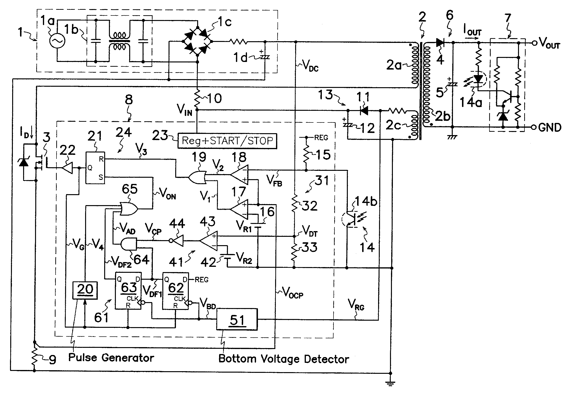
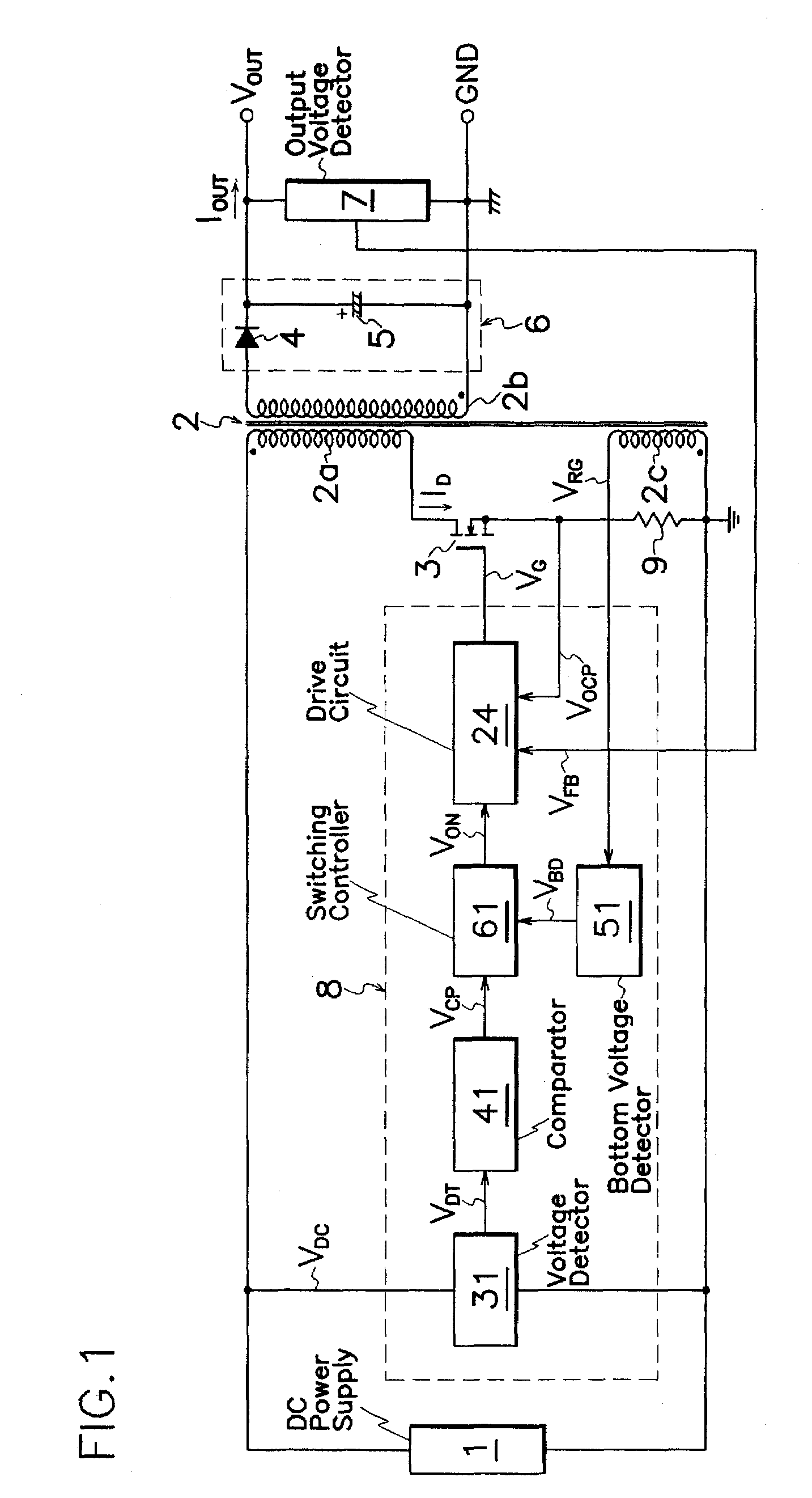
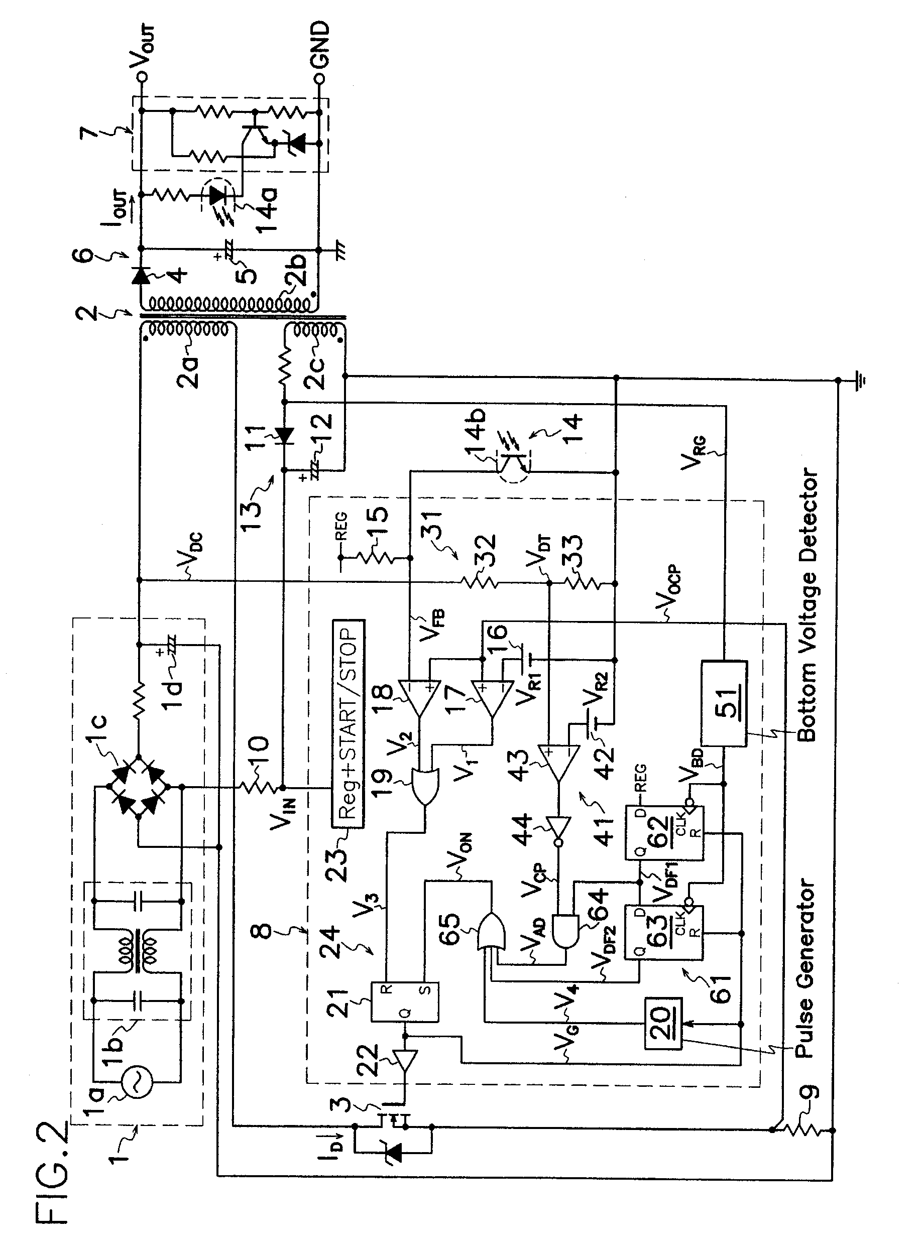
[0032]FIG. 1 shows the switching power source according to the present invention which comprises a DC power supply 1; a primary winding 2a of a transformer 2 and a MOS-FET (MOS type Field Effect Transistor) 3 as a switching element connected in series to DC power supply 1; an output rectifying smoother 6 which has an output rectifying diode 4 and an output smoothing capacitor 5 connected to a secondary winding 2b of transformer 2 to produce a DC output voltage VOUT; an output voltage detector 7 for detecting DC output voltage VOUT; a control circuit 8 which includes a drive circuit 24 for producing drive signals VG to MOS-FET 3 based on detection signals VFB from output voltage detector 7 to keep DC output voltage VOUT on a substantially constant level; and a current detecting resistor 9 for detecting electric current ID flowing through primary winding 2a of transformer 2 or MOS-FET 3 as a corresponding voltage to produce a detection signal VOCP to control circuit 8. Then, control c...

second embodiment

[0046 shown in FIG. 10 is advantageous in that RS-flip flop 45 can certainly keep the voltage level of comparative output signal from comparing circuit 43 to minimize power loss by input voltage detector 31 and further improve conversion efficiency in a wide fluctuation range of power source voltage. Incidentally, similar effects can be obtained in comparing an average or effective value of detection voltage VDT from AC input voltage VAC with reference voltage VR2 in lieu of comparing a peak value of detection voltage VDT from AC input voltage VAC with reference voltage VR2.

[0047]FIG. 11 represents a third embodiment of the switching power source according to the present invention. This power source comprises a level shift circuit 34 as an input voltage detector for detecting voltage VRG appearing on drive winding 2c of transformer 2 during the on period of MOS-FET 3, and a D-flip flop 47 adopted in place of inverter 44 in comparator 41 shown in FIG. 2. Level shift circuit 34 compri...

third embodiment

[0050]In the third embodiment, during the on period of MOS-FET 3, drive winding 2c of transformer 2 produces voltage VRG proportional to AC voltage supplied from AC power source 1a, and therefore, switching frequency of MOS-FET 3 can be controlled to an optimal frequency in response to AC voltage supplied from AC power source 1a by level-shifting circuit 34 which detects voltage VRG on drive winding 2c of transformer 2. As trailing edge of output signal VG from RS-flip flop 21 appears on the order of 50 to 500 nanoseconds earlier than turning off of MOS-FET 3, it is possible to avoid malfunction of comparator 41 resulted from switching noise occurring at the time of turning on or off of MOS-FET 3 by detecting voltage VRG from drive winding 2c of transformer 2 synchronously with trailing edge of output signal VG from RS-flip flop 21 and before turning on or off of MOS-FET 3.


PUM


Abstract

A control circuit 8 of a switching power source comprises a voltage detector 31 for detecting a voltage VDC of a DC power supply 1 to produce a detection voltage VDT; a comparator 41 for producing an output signal VCP when detection voltage VDT from voltage detector 31 exceeds a reference voltage VR2; a bottom voltage detector 51 for detecting a bottom point of voltage VDS across a MOS-FET 3 after energy has been discharged from transformer 2; and a switching controller 61 for selectively turning MOS-FET 3 on depending on existence or absence of the output signal VCP from comparator 41. When the input voltage VDC from DC power supply 1 so rises that detection voltage VDT of voltage detector 31 is above the reference voltage VR2, switching controller 61 serves to late turn MOS-FET 3 on at the time bottom voltage detector 51 detects the second or later bottom point of the voltage VDS across MOS-FET 3, extending the off period of MOS-FET 3 to reduce switching frequency of MOS-FET 3.

Description

CROSS-REFERENCE TO RELATED APPLICATION[0001]The instant application is a continuation-in-part of U.S. application Ser. No. 10 / 525,894 filed Feb. 25, 2005 and which issued on Apr. 25, 2006 as U.S. Pat. No. 7,035,119.TECHNICAL FIELD[0002]This invention relates to a switching power source capable of improving the conversion efficiency in a wide variation range of power voltage.BACKGROUND OF THE INVENTION[0003]Prior art switching power sources of flyback pseudo resonance (partial voltage resonance) type have been utilized in wide applications because they advantageously have a simplified circuit structure with the high conversion efficiency and less operating noise. For example, Japanese Patent Disclosure No. 2003-61345 discloses a switching power source of such a pseudo resonance type which, however, has their defect in that change in input voltage from commercial AC power source fluctuates switching frequency of a switching element under the constant load. For example, in a switching ...

Claims


Application Information

Patent Timeline
Patent Type & Authority Patents(United States)
IPC IPC(8): H02M3/335H02M3/28H02M1/10
CPCH02M3/33523H02M1/10
Inventor KOIKE, KENGO
Owner SANKEN ELECTRIC CO LTD
Why Eureka
Try Eureka