Drive control device and image forming apparatus including the same
a technology of drive control and image forming apparatus, which is applied in the direction of electrographic process apparatus, instruments, printing, etc., can solve the problems of inability to accurately control the movement or the speed of the movable member moving is apt to vary, and it is difficult to execute accurate control of the movement or the position of the movable member
- Summary
- Abstract
- Description
- Claims
- Application Information
AI Technical Summary
Benefits of technology
Problems solved by technology
Method used
Image
Examples
modification 1
[0078] [Modification 1]
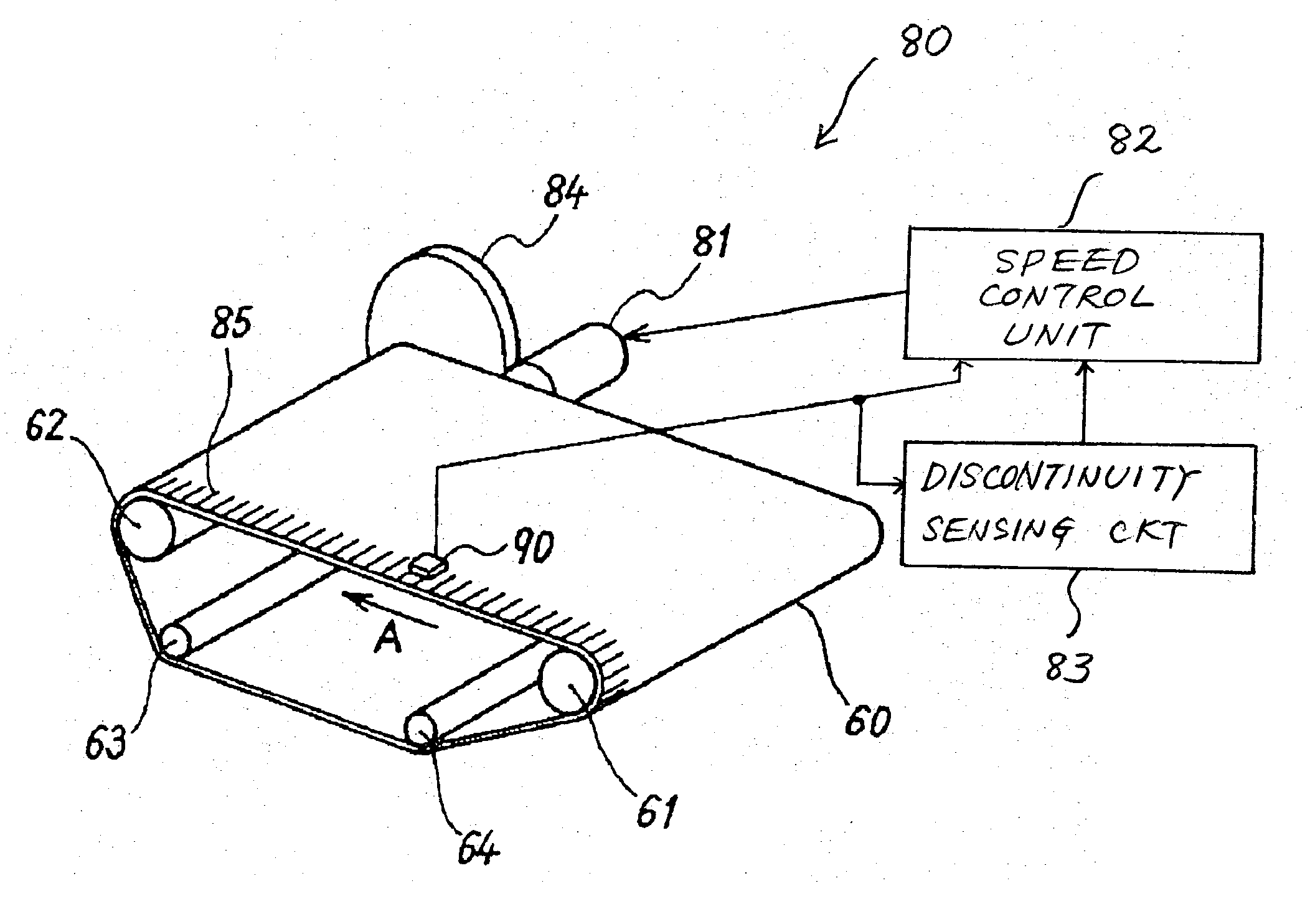
[0079] FIG. 11 shows Modification 1 of the illustrative embodiment. As shown, the drive control section includes a dummy signal generator or generating means 187 and a speed control unit or speed / position control means 182 in addition to the mark sensor 90 and discontinuity sensing circuit 83. The speed control unit 182 includes a PLL controller 183 similar to that of the illustrative embodiment and a signal selector or signal switching means 184. In Modification 1, the PLL controller 183 does not have to be ON / OFF controlled by an external signal and is therefore low cost.
[0080] The dummy signal generator 187 generates a dummy signal repeatedly appearing at a period identical with the mean interval of the mark sense signals derived from the continuous mark portion. More specifically, the dummy signal generator 187 samples a plurality of mark sense signals derived from the continuous mark portion, calculates a mean value over the sampling interval, and generat...
modification 2
[0084] [Modification 2]
[0085] Modification 2 will be described with reference to FIG. 13. In Modification 1 described above, the phase of the mark sense signal and that of the dummy signal are not matched to each other. This brings about a problem that if the two phases are shifted from each other, then the phase of the repeating pulse signal input to the PLL controller 183 is apt to jump for a moment in relation to the signal switching timing of the signal selector 184, causing the above phase to be noticeably shifted from the phase of the reference clock. Modification 2 is so configured as to reduce the jump of the phase of the repeating pulse signal input to the PLL controller 183, as will be described hereinafter.
[0086] As shown in FIG. 13, the drive control section includes a speed control unit or speed / position control means 282 in addition to the mark sensor 90 and discontinuity sensing circuit 83. The speed control unit 282 includes a speed calculator 287, a speed / frequency ...
modification 3
[0093] [Modification 3]
[0094] Reference will be made to FIG. 14 for describing Modification 3 of the illustrative embodiment. As shown, a drive control section includes a speed control unit or speed / position control means 382 in addition to the mark sensor 90 and discontinuity sensing circuit 83. The speed control unit 282 includes a controller 383, an F / V (frequency-to-voltage) converter 388, and a voltage control circuit 384. The controller 383 sends to the belt motor 81 a drive signal corresponding to the feedback signal derived from the mark sensor 90.
[0095] More specifically, the controller 383 includes a reference signal terminal to which a reference voltage or reference signal is input and a comparison signal terminal to which a voltage signal output from the voltage control circuit 384 is input. The reference voltage is matched to the target moving speed of the belt 60. The controller 383 compares the reference voltage and the voltage signal output from the voltage control c...
PUM
 Abstract
Description
Claims
Application Information
 - R&D
- Intellectual Property
- Life Sciences
- Materials
- Tech Scout
- Unparalleled Data Quality
- Higher Quality Content
- 60% Fewer Hallucinations
Browse by: Latest US Patents, China's latest patents, Technical Efficacy Thesaurus, Application Domain, Technology Topic, Popular Technical Reports.
© 2025 PatSnap. All rights reserved.Legal|Privacy policy|Modern Slavery Act Transparency Statement|Sitemap|About US| Contact US: help@patsnap.com


