Fuel transporting device for a motor vehicle

a technology for transporting devices and motor vehicles, which is applied in the direction of positive displacement liquid engines, piston pumps, separation processes, etc., can solve the problems of complex production and storage and achieve the effect of improving the efficiency of the fuel feed system

Inactive Publication Date: 2004-02-26
ROBERT BOSCH GMBH
View PDF9 Cites 15 Cited by
  • Summary
  • Abstract
  • Description
  • Claims
  • Application Information

AI Technical Summary

Problems solved by technology

A disadvantage of the known fuel feed system is that the pumping part is integrated with the housing, so that for various embodiments of a pumpin

Method used


Image

  • Fuel transporting device for a motor vehicle
  • Fuel transporting device for a motor vehicle
  • Fuel transporting device for a motor vehicle

Examples


Embodiment Construction

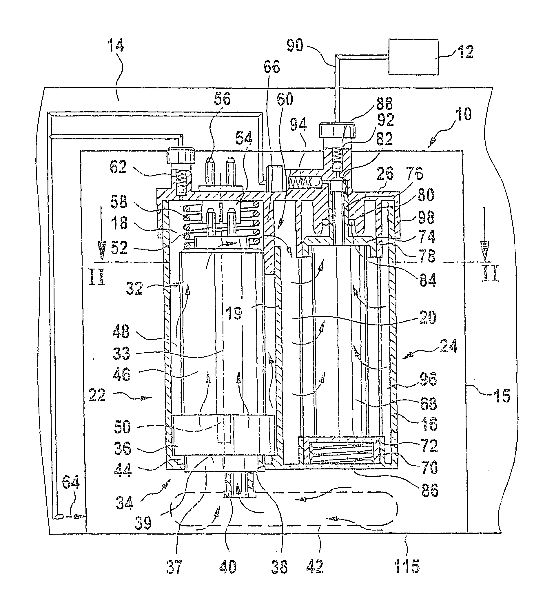
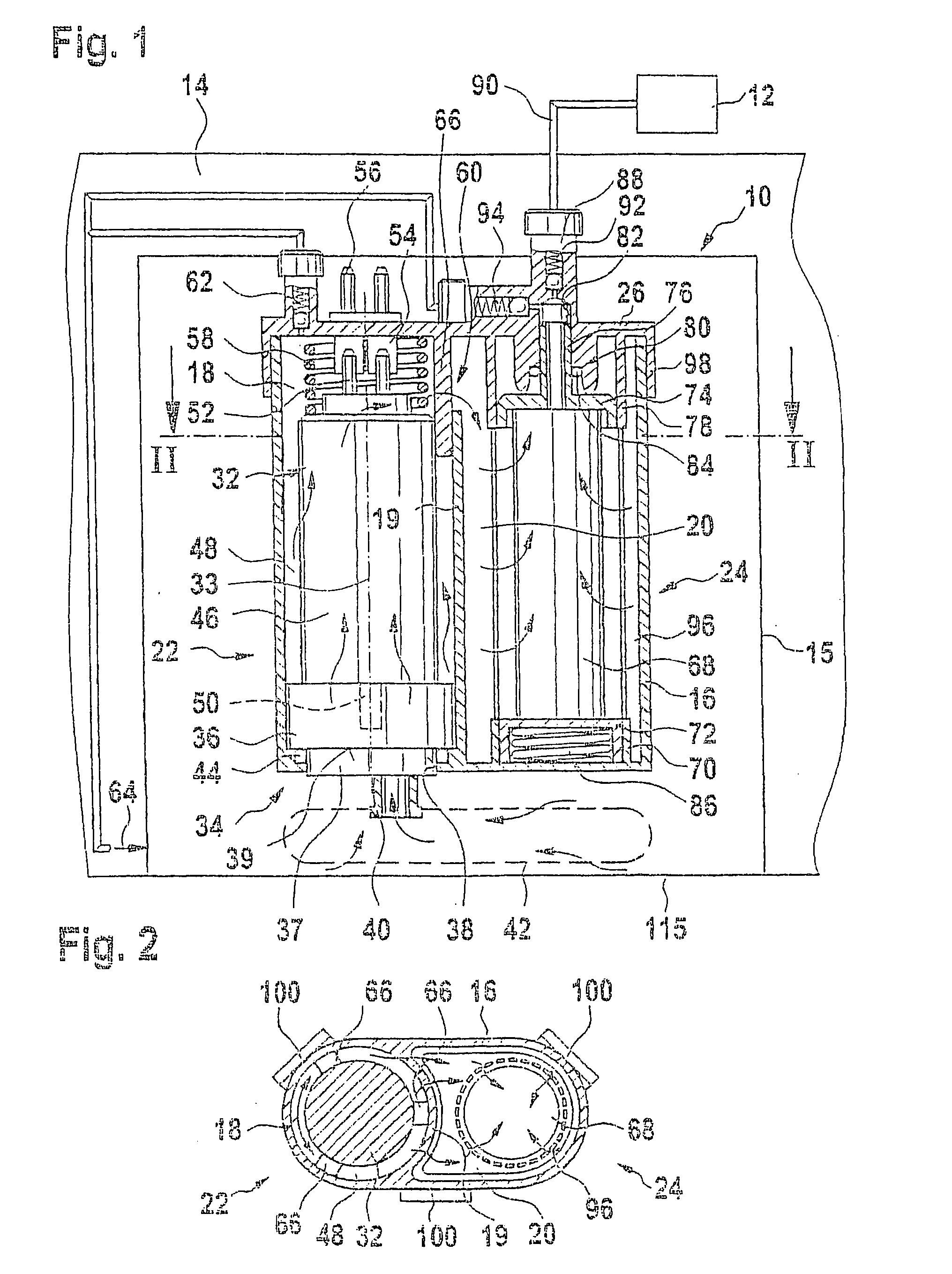
[0015] In FIGS. 1 and 2, a fuel feed system 10 for a motor vehicle is shown. The motor vehicle has an internal combustion engine 12 with an injection system, through which fuel is injected into the cylinders of the engine 12. The fuel feed system 10 is disposed in a fuel tank 14 of the motor vehicle. A cup-shaped storage container 15 can be disposed in the fuel tank 14; it has a substantially smaller volume than the fuel tank 14, and the fuel feed system 10 is disposed in it. The storage container 15 is not necessary, if a cup-shaped indentation is embodied in the bottom 115 of the fuel tank 14. The fuel feed system 10 has a housing 16, in which two separate cup-shaped chambers 18 and 20 disposed side by side are formed, divided from one another by a chamber wall 19. A feed unit 22, described in further detail hereinafter, is disposed in the first chamber 18, and a filter 24, also described in further detail hereinafter, is disposed in the second chamber 20. The housing 16 is tightl...


PUM

PropertyMeasurementUnit
Resilienceaaaaaaaaaa

Abstract

The fuel feed system has a feed unit (22), which has having an electric motor (32) as a drive mechanism and a pumping part (34) driven by the electric motor; the pumping part (34) is disposed offset from the electric motor (32), in the direction of the pivot axis (33) of the electric motor. A filter (24) is disposed beside the feed unit (22) and fuel pumped by the pumping part (34) flows through it. The feed unit (22) and the filter (24) are disposed in separate chambers (10, 20) of a common housing (16), between which chambers there is an overflow opening (60) for the fuel pumped by the pumping part (34). The housing (16) is tightly closed by means of a cap (26). The electric motor (32) and the pumping part (34) are inserted as separate structural units into a chamber (10) of the housing (16) and are braced against one another by at least one resilient element (58) in the direction of the pivot axis (33) of the electric motor (32).

Description

PRIOR ART[0001] The invention based on a fuel feed system for a motor vehicle as generically defined by the preamble to claim 1.[0002] One such fuel feed system is known from German Patent Disclosure DE 42 42 242 A1. This fuel feed system has a feed unit with an electric motor as a drive mechanism and with a pumping part driven by the electric motor. The pumping part is offset toward the electric motor in the direction of the pivot axis of the electric motor. The fuel feed system also has a filter, which is disposed beside the feed unit and through which fuel pumped by the feed unit flows. The fuel feed system has a housing, in which the feed unit and the filter are disposed in separate chambers. Between the chambers, there is an overflow opening for the fuel pumped by the feed unit. The housing is tightly closed with a cap. A disadvantage of the known fuel feed system is that the pumping part is integrated with the housing, so that for various embodiments of a pumping part, separat...

Claims


Application Information

Patent Timeline
IPC IPC(8): F02M39/00F02M37/04F02M37/10F02M37/44F02M37/46F02M37/48F02M37/50
CPCF02M37/106F02M2037/228F02M37/22F02M37/50F02M37/44F02M37/46F02M37/48F02M37/10
Inventor SCHELHAS, PETERREICHL, ASTAKLEPPNER, STEPHANKUEHN, MICHAELROLLWAGEN, MATHIASBRAUN, HANS-PETERFEES, HANS-JOERGSCHRECKENBERGER, DIETERWIELAND, THOMASROSE, JOCHEN
Owner ROBERT BOSCH GMBH
Why Eureka
Try Eureka