Therapeutic bio-energy unit

a bio-energy unit and bio-energy technology, applied in the field of therapeutic bio-energy units, can solve problems such as skin irritation

Inactive Publication Date: 2004-02-26
WODNICKI JANUSZ
View PDF1 Cites 6 Cited by
  • Summary
  • Abstract
  • Description
  • Claims
  • Application Information

AI Technical Summary

Benefits of technology

[0013] It is an object of the present invention to provide a unit which is not harmful and which can be used more easily.

Problems solved by technology

The above defined inserts and soles exercise mechanical impact upon the reaction spheres of the foot, and may result in skin irritations.

Method used


Image

  • Therapeutic bio-energy unit
  • Therapeutic bio-energy unit
  • Therapeutic bio-energy unit

Examples


Embodiment Construction

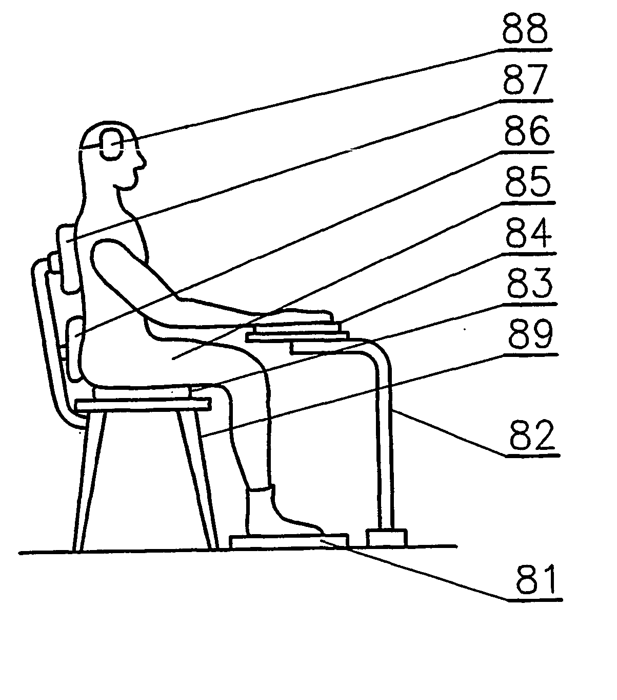
[0045] The invention shall be described in detail in relation to the bio-energy carpeting pad, and in particular in relation to the backbone system, though it may also have the form of shoulder or loin system, as shown diagrammatically in the enclosed figures. In the final section, the invention shall be described in relation to subsystems and elements in public transport vehicles, the elements of game machines, sections of electric appliances, telecommunication and computer equipment, including the frame, keyboard, mouse, mouse pad, as well as laptops and mobile phones.

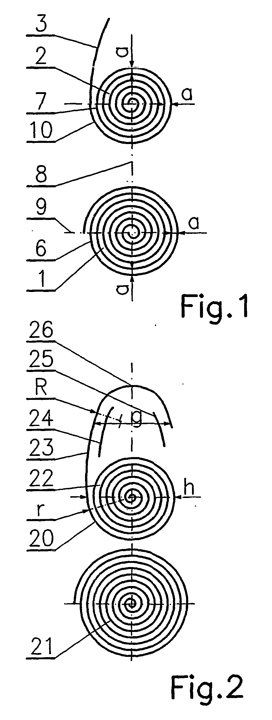
[0046] FIG. 1 shows the double-spiral energising module. Its spiral 1 has counter-clockwise (laevorotary) coil, and spiral 2 has clockwise (dextrorotary) coil. The distances a between the coils 6 of spiral 1, measured along the axes 8, 9 and the coils 7 of spiral 2 are equal. The external coil 10 of the clockwise spiral 2 leads to segment 3 having small curvature.

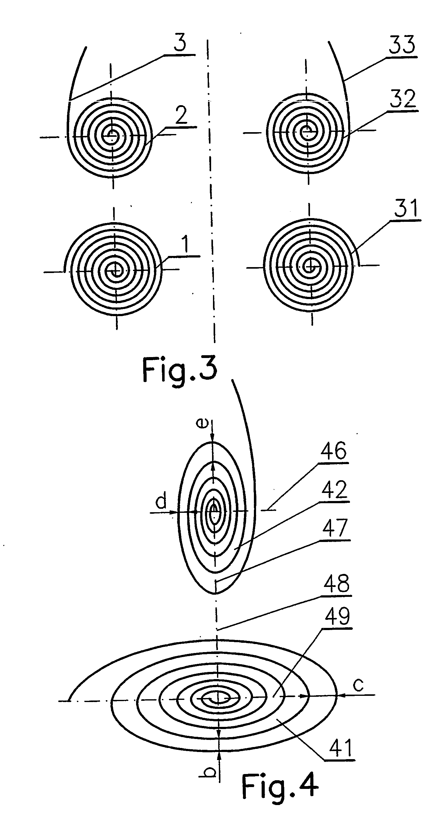
[0047] FIG. 2 shows a four-element energising module c...


PUM


Abstract

A therapeutic bio-energy unit has at least one energising module, which consists of at least two spirals (21, 22), one of which has an external coil (20), which leads to a segment (23) showing slight curvature. The segment (23) of slight curvature leads next to the closing curve (26) which is convex towards the spiral (22) and which circles two curvilinear energising elements (24, 25), which are convex towards the closing curve (26), and which are the

Description

[0001] 1. Field of the Invention[0002] The present invention relates to a therapeutic bio-energy unit used in therapy through application of magnetic or electromagnetic field.[0003] 2. Brief Description of the Background of the Invention Including Prior Art[0004] Polish patent description No. 124 434 shows a therapeutic unit relying on pulsating electric currents. The unit consists of the relaxation generator linked--through formation set--with the amplitude modifier powered with alternate current, and two terminal current amplifiers, which are connected to a pair of procedure electrodes applied directly on the patient's body. The terminal current amplifiers of the unit are galvanically separated from each other, and from the power system supplying the amplitude modifier.[0005] Polish patent description No. 154 986 shows the method and equipment unit applied in non-intervention diagnosis of human internal organs, through the measurement of electric properties displayed by particular...

Claims


Application Information

Patent Timeline
Patent Type & Authority Applications(United States)
IPC IPC(8): A61N1/40A61N2/02A61N2/04
CPCA61N2/02A61N1/40
Inventor WODNICKI, JANUSZ
Owner WODNICKI JANUSZ
Why Eureka
Try Eureka