Common mode feedback technique for a low voltage charge pump

a low-voltage charge pump and feedback technology, applied in the field of charge pumps, can solve the problems of cmos transistor elements often showing slight variations in performance, undesirable variations in phase error signals, and errors in the charge pump circuitry

Inactive Publication Date: 2004-03-04
INTEL CORP
View PDF0 Cites 22 Cited by
  • Summary
  • Abstract
  • Description
  • Claims
  • Application Information

AI Technical Summary

Problems solved by technology

One source of errors in PLLs is the charge pump circuitry.
The CMOS transistor elements often exhibit slight variations in performance due to mechanical manufacturing discrepancies.
Such discrepancies may result in undesirable variations in the phase error signals.
Additionally, variations in the power supply used to power or bias the transistor elements also may result in undesirable variations, or jitter, in the charge pump signal.

Method used


Image

  • Common mode feedback technique for a low voltage charge pump
  • Common mode feedback technique for a low voltage charge pump
  • Common mode feedback technique for a low voltage charge pump

Examples


Embodiment Construction

[0013] Reference in the specification to "one embodiment", "an embodiment", or "another embodiment" of the present invention means that a particular feature, structure or characteristic described in connection with the embodiment is included in at least one embodiment of the present invention. Thus, appearances of the phrase "in one embodiment" or "according to an embodiment" appearing in various places throughout the specification are not necessarily all referring to the same embodiment. Likewise, appearances of the phrase "in another embodiment" or "according to another embodiment" appearing in various places throughout the specification are not necessarily referring to different embodiments.

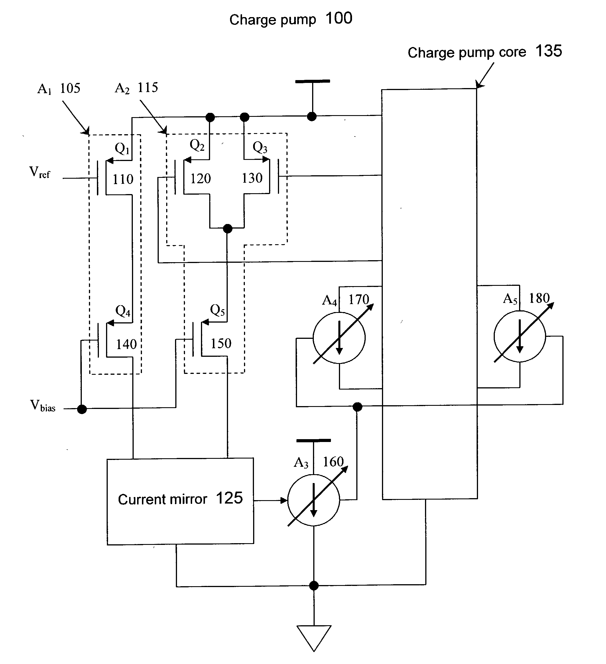
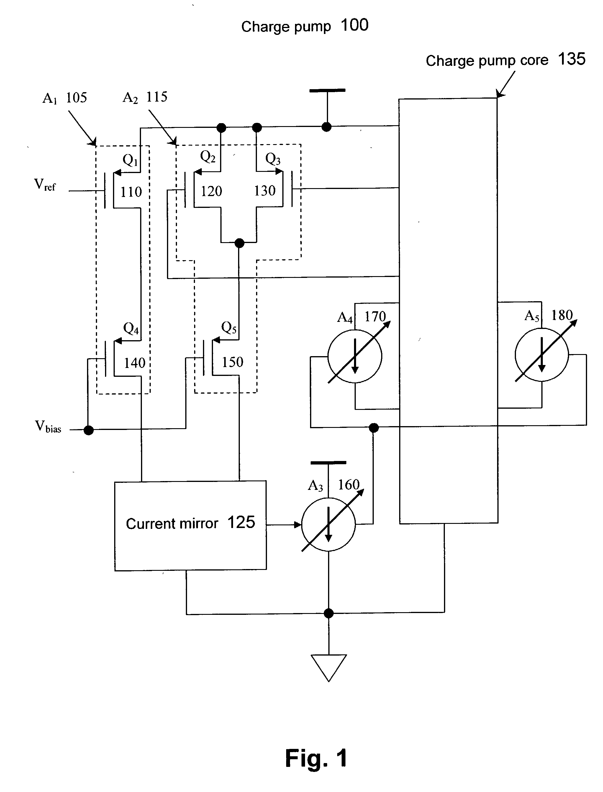
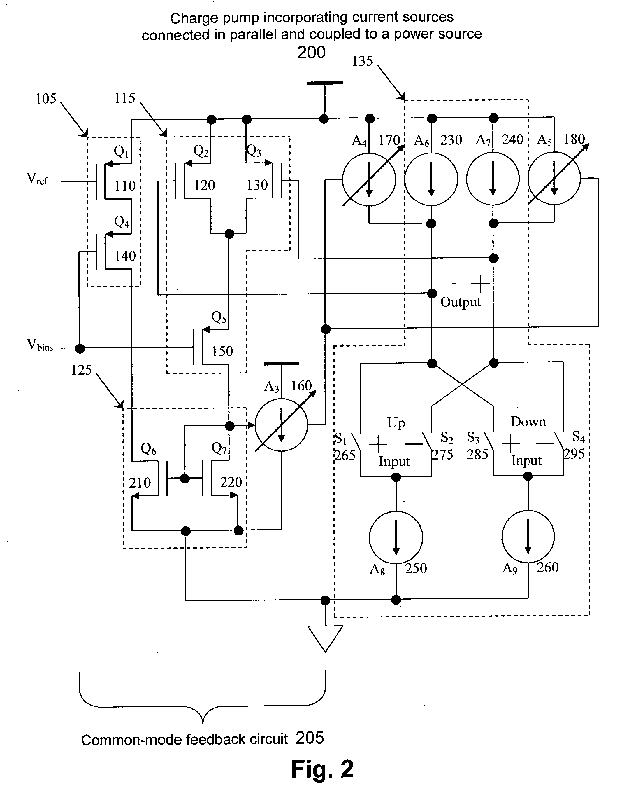
[0014] FIG. 1 illustrates a charge pump according to an embodiment of the present invention. The charge pump 100 includes a current mirror 125, a first current source 105, and a second current source 115. The first current source 105 may include a transistor 110 and a transistor 140. The trans...


PUM


Abstract

A charge pump includes a first current source, a second current source, and a current mirror. The first current source is included to set a common mode output voltage of a charge pump core based on a desired common mode input of the charge pump core. The second current source is included to receive the common mode output voltage from the charge pump core. A first input of the current mirror receives a signal from the first current source, and a second input of the current mirror receives a signal from the second current source.

Description

BACKGROUND[0001] 1. Technical Field[0002] An embodiment of the present invention generally relates to a charge pump. More particularly, an embodiment of the present invention relates to a charge pump having a common mode feedback.[0003] 2. Discussion of the Related Art[0004] Electronic circuits that provide clock signals are used in a wide range of data systems, such as computer systems and digital data communication systems. Such systems generally operate at relatively high frequencies at which data bandwidth is at a premium. A phase-locked loop ("PLL") may be used, for example, as part of a clock recovery unit, to derive a clock signal from incoming data signals. For instance, a PLL may be used to synchronize, or de-skew, an internal control clock with respect to an external system clock.[0005] A PLL may include a phase / frequency detector ("PFD"), a charge pump, a low-pass filter, and a voltage-controlled oscillator ("VCO"). The PFD compares two input signals, a reference signal f...

Claims


Application Information

Patent Timeline
Patent Type & Authority Applications(United States)
IPC IPC(8): H03L7/089
CPCH03L7/0896
Inventor ABIDIN, CINDRA W.ASMANIS, GEORGIOS S.
Owner INTEL CORP
Why Eureka
Try Eureka