Dielectric waveguide type filter and branching filter
a branching filter and waveguide technology, applied in the direction of waveguides, electrical devices, coupling devices, etc., can solve the problems of less reliability, apt to be caused between the conductive vias, and the filter having the abovementioned structure is very difficult to manufactur
- Summary
- Abstract
- Description
- Claims
- Application Information
AI Technical Summary
Problems solved by technology
Method used
Image
Examples
example 2
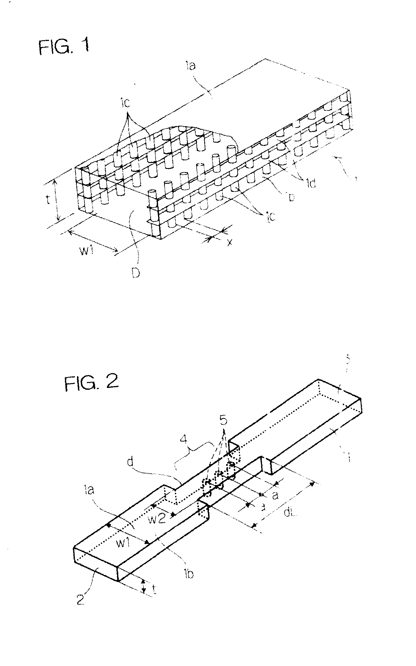
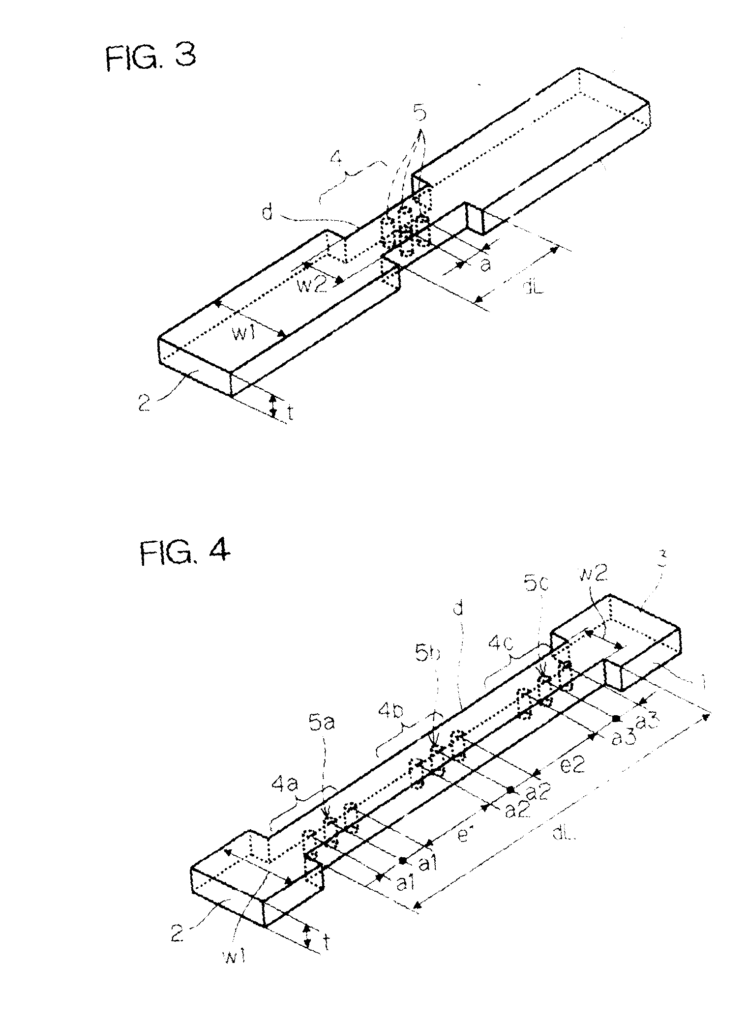
[0097] A dielectric waveguide type filter shown in FIG. 3 was manufactured. The transmittance characteristic of the filter is shown in FIG. 6. Parameters of the filter were as follows. Parameters of the basic dielectric waveguide were the same with those of Example 1. Of the resonator 4, the width of the cutoff waveguide w.sub.2=0.8 mm, the length of the cutoff waveguide path dL=2.0 mm, the dielectric constant of the dielectric in the dielectric vias .epsilon.d=20.0, the dielectric via diameter b=.phi.0.2 mm, and the dielectric via pitch (center distance) a=0.4 mm. Further, the dielectric vias 5 were arranged in a column along the central axis of the cutoff waveguide path d.
[0098] In this case, a characteristic that the resonant frequency is 74.1 GHz and the transmittance frequency band width is 0.9 GHz was obtained, and it proves that such a structure functions as a filter. It is understood in comparison with Example 1 that the transmittance characteristic can be controlled by cont...
example 3
[0099] A dielectric waveguide type filter shown in FIG. 4 was manufactured. The transmittance characteristic of the filter is shown in FIG. 7. Parameters of the filter were as follows. Parameters of the basic dielectric waveguide were the same with those of Example 1. Of the resonator 4, the width of the cutoff waveguide w.sub.2=0.8 mm, the length of the cutoff waveguide path dL=7.2 mm, the dielectric constant of the dielectric vias 5a, 5b, 5c, .epsilon.d=20.0, the dielectric via diameter b=.phi.0.2 mm, the dielectric via pitches a.sub.1, a.sub.2, a.sub.3=0.5 mm, and the distances between the via groups e.sub.1=1.57 mm, e.sub.2=1.57 mm. Further, the dielectric via groups of the resonators 4a, 4b, 4c were arranged in a column along the central axis of the cutoff waveguide path respectively. Further, the dielectric via group of the resonators 4 was arranged at a position displaced by 0.03 mm from the central axis of the cutoff waveguide path.
[0100] In this case, a characteristic that ...
PUM
 Abstract
Description
Claims
Application Information
 - R&D
- Intellectual Property
- Life Sciences
- Materials
- Tech Scout
- Unparalleled Data Quality
- Higher Quality Content
- 60% Fewer Hallucinations
Browse by: Latest US Patents, China's latest patents, Technical Efficacy Thesaurus, Application Domain, Technology Topic, Popular Technical Reports.
© 2025 PatSnap. All rights reserved.Legal|Privacy policy|Modern Slavery Act Transparency Statement|Sitemap|About US| Contact US: help@patsnap.com


