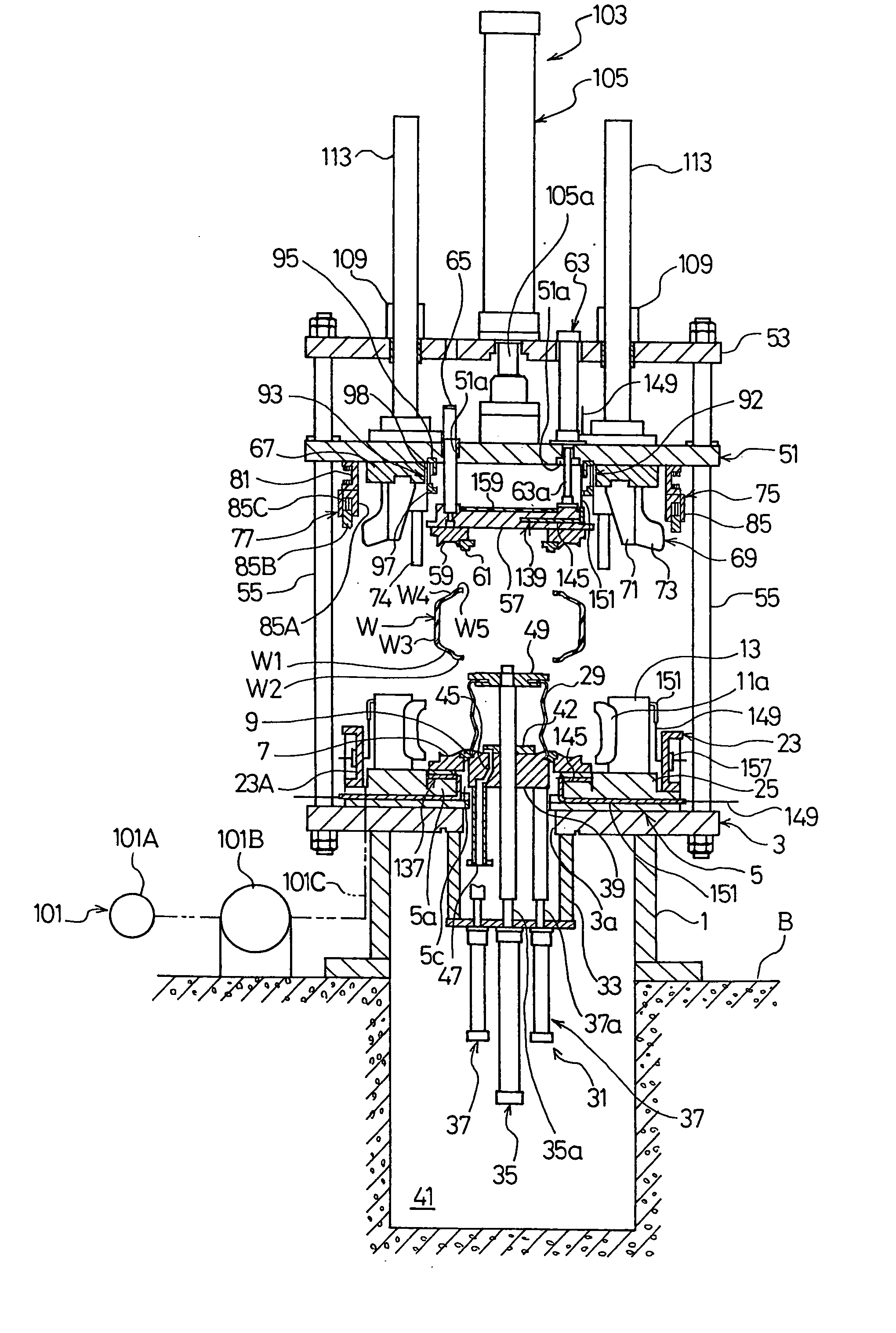
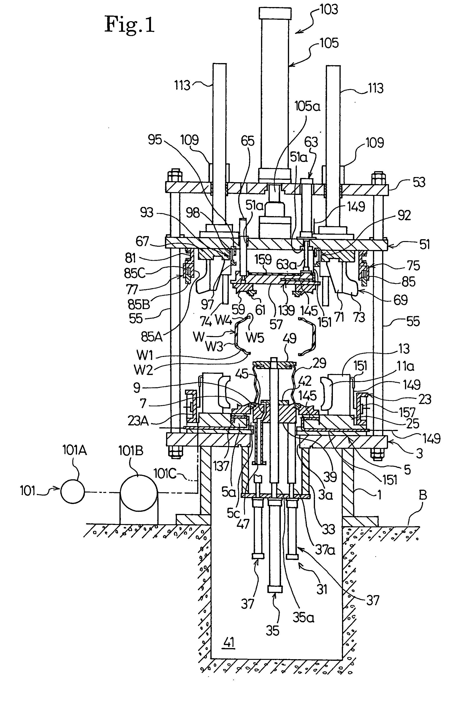
[0093] According to the present invention, since the sectors 11a and the holding segments 13 are not attached to the upper plate 51 side, but are mounted to the lower plate 5 side, the weight of the components supported by the upper plate 51 decreases much less than that of the components in the prior art. The upper plate 51 which supports the components can, therefore, be thinner, thereby allowing the upper plate 51 to be reduced in size as well as in weight. Also, the columns 55 slidably supporting the upper plate 51 can be thinner in
diameter and the top plate 53 supporting the upper plate 51 via the
hydraulic cylinder 105 can be smaller in thickness than before. Further, the
hydraulic cylinder 105 can have the capacity much less than the prior art. Accordingly, the tire press can be minimized in size, and the space for installing the tire press can be reduced. Also,
electric power consumed by the lifting means 103 for the upper plate 51 is reduced, thereby allowing a decrease in
power consumption.
[0094] Since the holding segments 13 are always in engagement with the guide rails 15 of the lower plate 5 side and do not have a structure such as the prior art in which the holding segments engage therewith and disengage therefrom, the clearance between the holding segments 13 and the guide rails 15 can be smaller than that of the prior art. Accordingly, movement of the sectors 11a due to pressure applied to the sectors 11a from the radially inner side can be less than is known in the prior art, thereby allowing
tire uniformity to be improved.
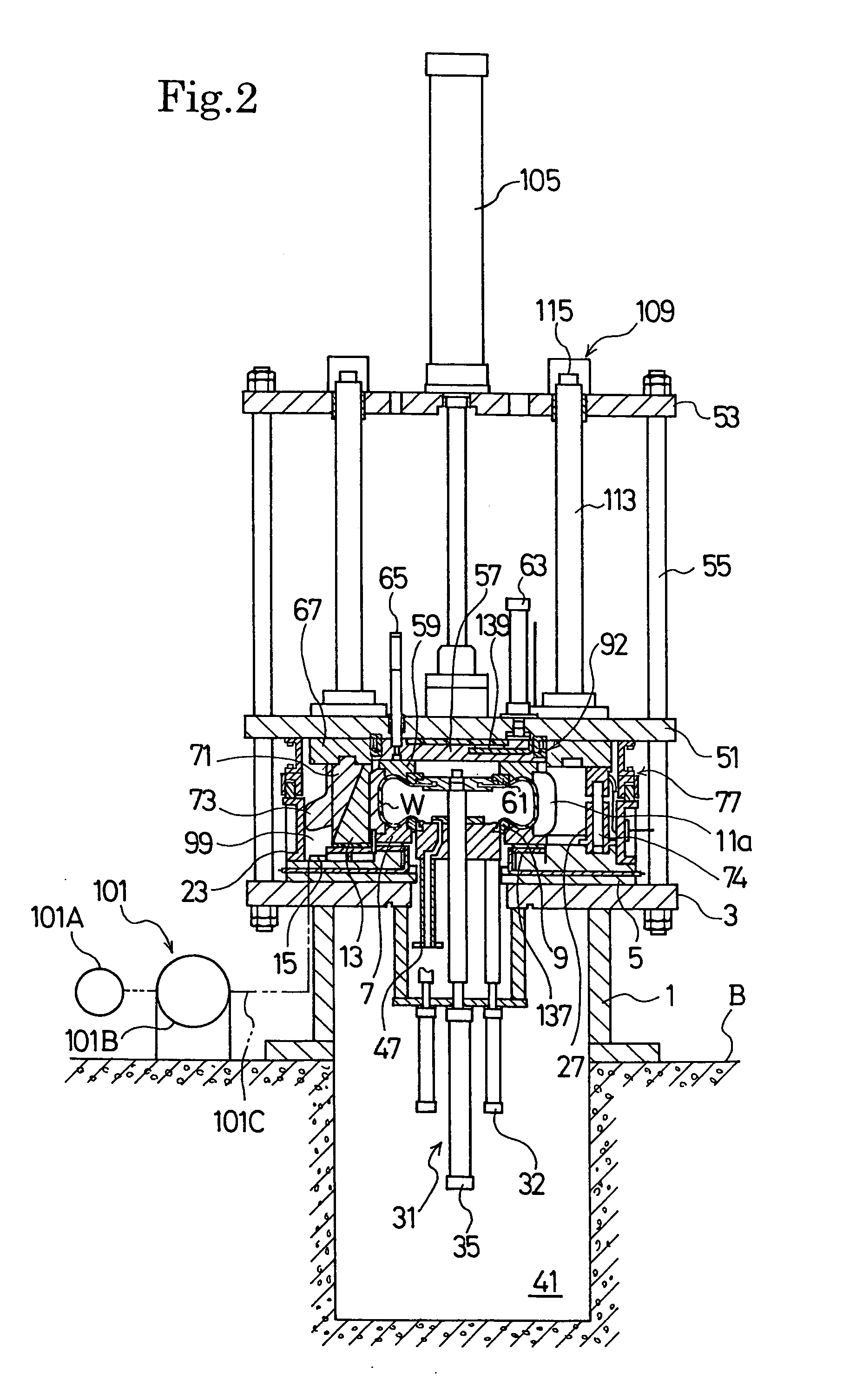
[0095] Since the electric heaters 143 are employed as means for heating the green tire W in place of conventional steam means, the tire press can be much smaller in size. By disposing the electric heaters 143 of the first, second and third heating means 137, 139 and 141 in the above positions, respectively,
temperature control during
vulcanization can be performed independently, which can effectively heat the green tire W to thereby shorten the
curing time.
[0096] There is provided between the upper plate 51 and the lower plate 5 the first sealing means 75 which hermetically covers the entire mold during
vulcanization, and air in the chamber 99 hermetically covered with the first sealing means 75 is sucked by the suction means 101 to make the chamber vacuum, thereby allowing
trapped air between the green tire W and the mold in engagement therewith to be significantly reduced. When air is trapped between the mold and the green tire W, the air causes the tire surface to be rugged after
vulcanization, resulting in a poor appearance. As mentioned above, since the
trapped air can noticeably be reduced, appearance of the tire obtained after curing can be improved. Also, since the pressure (inner pressure) of a thermal pressurized fluid supplied to the bladder 29 can be lowered, the pressure which is applied to the upper mold section 59 and the sectors 11a and which acts as a mold opening pressure is reduced. As a result, since stiffness and strength of the components which hold the upper mold section 59 and the sectors 11a in the mold clamping position can be lowered, the cost of the components is reduced, thereby allowing a decrease in tire press cost. Also, a tire quality can be improved because the green tire W pressed by the bladder 29 is restrained from changing the angle of the reinforcement cords of the belt
layers and carcass layer thereof, and from causing variations in thickness.
[0097] Since the holding segments 13 are provided via the linear bearings 17 on the guide rails 15 in an advancable and retractable manner, the holding segments can smoothly move along the guide rails and the looseness therebetween can be restrained. Accordingly, movement of the sectors 11a by the inner pressure during vulcanization can be reduced, thereby improving a tire quality.
[0098] The holding segments 13, which are slidably located on the guide rails 15, may move due to vibration or the like; by providing the positioning means 161 which position the holding segments 13 in the engagement position with the guide segments 69, the holding segments 13 can reliably be engaged with the guide segments 69 at all times, preventing a trouble at the clamping of the mold from happening.
[0104] In the embodiment shown in FIG. 23, the same number and even number of guide segments 69, holding segments 13 and sectors 11a are employed, and the number thereof may preferably be, for example, eight, ten or twelve.
[0105] In FIG. 23, the locking means 109 and the locking shafts 113 are not shown, but they are placed at locations in which they do not vertically overlap the lifting means 171.
[0106] As mentioned above, according to the present invention, since the sectors and the holding segments are mounted to the lower plate side, the weight of the components supported by the upper plate is reduced much less than that of the components in the prior art. As a result, the upper plate which supports the components can be reduced in size as well as in weight less than before. Associated components which liftably support the upper plate can also be reduced in size and in weight, and further, lifting means lifting the upper plate can be smaller in size. Accordingly, the tire press can be small-sized, and the installation space therefor can be reduced. Also, since the
electric power consumed by the means for lifting the upper plate is reduced,
power consumption can be lowered.
[0107] Since the holding segments are always in engagement with the lower plate side and do not have a conventional structure in which the holding segments engage therewith and disengage therefrom, the clearance between engagement parts can be smaller than that of the prior art. As a result, movement of the sectors is less than before at the mold clamping position when pressure is applied thereto from the radially inner side thereof during vulcanization, thereby allowing
tire uniformity to be improved.
[0108] The present invention having the aforementioned excellent effects can be used very effectively as a tire curing method and tire press for producing pneumatic tires for passenger cars, trucks, buses and the like.

