Image capturing device with reflex reduction

a technology of image capturing and reflex reduction, which is applied in the field of image capturing devices with reflex reduction, can solve the problems of affecting the light, difficult computer processing of images, and constant change of images of objects

Inactive Publication Date: 2004-03-11
SMART EYE
View PDF4 Cites 92 Cited by
  • Summary
  • Abstract
  • Description
  • Claims
  • Application Information

AI Technical Summary

Problems solved by technology

When capturing images, especially images intended for automatic analysis, several problems related to the light conditions are present, making computer treatment of the images difficult.
To begin with, in some cases the light conditions are difficult or transient, resulting in the images of an object constantly changing.
Further, parts of the object may be hidden behind obstacles which affect the light.
These and other problems can in some cases lead to difficulties in acquiring high quality images or performing a desired analysis of the images.
A problem with this technique occurs, however, when areas of enhanced reflection are present in the object, this often being the case when the object has a varying surface structure and reflection coefficient (e.g. a face).
This problem is present also when using conventional video cameras, as light from e.g. a window may be reflected in the object, and thereby cause difficulties in the detection.
However, this problem is further emphasized when exposing the object with active radiation, as use of reflected waves is the basic principle underlying the whole idea.
When the reflection is disturbed, or varies over the object, the processing of images is affected negatively.
Unfortunately, any type of glasses or visors present one of the most significant sources of disturbing reflexes, thus making successful detection through sunglasses difficult still.
The above problems are especially troublesome in this field of technology, as the requirements on the image quality in some cases are very high.
Finally, users are often wearing glasses, and even more disturbing, sunglasses, hiding the eyes.
If the purpose of the image capturing is to detect information about the eyes of a user, such as gaze direction, based on images of his / her face, these problems can be serious.

Method used


Image

  • Image capturing device with reflex reduction
  • Image capturing device with reflex reduction
  • Image capturing device with reflex reduction

Examples


Embodiment Construction

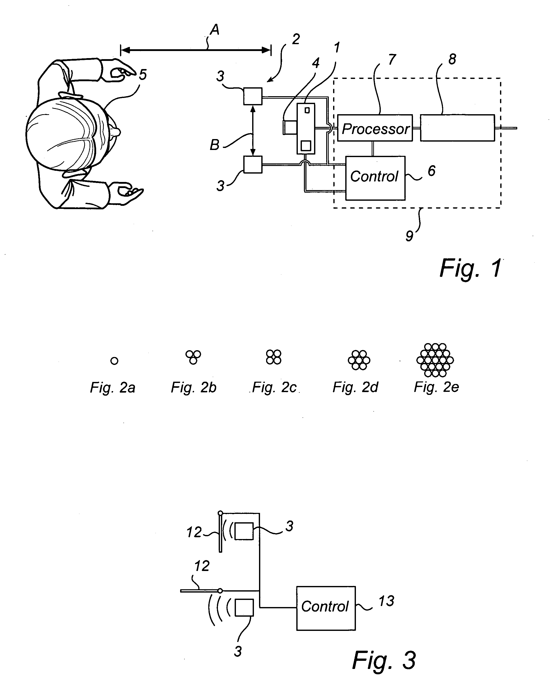
[0035] FIG. 1 illustrates an arrangement for capturing images of a face 5, with a device according to a first embodiment of the invention, especially adapted for detection of the bright eye effect of the eyes. In this case, a camera 1 with an electronic image sensor is used as image capturing device, and the wave emitter 2 comprises two separate wave sources 3.

[0036] The camera is preferably a conventional electronic image sensor camera, either of snapshot type or delivering a stream of consecutive images (i.e. a video camera). The images can be in a digital format, e.g. a bitmap format, or in analog form which then can be converted to a digital format, e.g. using a framegrabber circuit.

[0037] The electromagnetic waves emitted by the wave sources can be of different types, including IR radiation. In some cases it is preferred that the waves are within a relatively narrow wave length range outside the range of visible light, and that the camera is provided with a band pass filter 4 c...


PUM


Abstract

The present invention relates to an image capturing device for reflex reduction, comprising at least one wave emitter (2) for emitting electromagnetic waves towards the object and at least one image capturing device (1), directed towards the object. The wave emitter (2) is arranged to emit said waves towards the object alternately from at least two points, said points being separated such a distance (B) that disturbing reflexes, resulting from waves emitted from different points and appearing in an image captured with said image capturing device, are seperable. Further, the device comprises processing means (7), adapted to receive at least two images, acquired with illumination from different angles, and to generate a reflex reduced image.

Description

[0001] In its most general form, the present invention relates to an image capturing device with reflex reduction, comprising at least one wave emitter for emitting electromagnetic waves towards an object and at least one image capturing device, directed towards the object.[0002] More specifically, the invention relates to a device for eye detection of a person (for example relative position of eyelids, the position of the eyes, iris and eye corners, the bright eye effect etc), also comprising a computer processor, for processing images from said image capturing device of the face of the person and determining the required information from said images.TECHNICAL BACKGROUND[0003] When capturing images, especially images intended for automatic analysis, several problems related to the light conditions are present, making computer treatment of the images difficult. To begin with, in some cases the light conditions are difficult or transient, resulting in the images of an object constant...

Claims


Application Information

Patent Timeline
Patent Type & Authority Applications(United States)
IPC IPC(8): A61B3/113A61B3/14
CPCA61B3/14A61B3/113
Inventor RYDBECK, BO
Owner SMART EYE
Why Eureka
Try Eureka