Optical switching subsystem and optical switching subsystem self-diagnosing method

a technology of optical switching subsystem and optical switching subsystem, which is applied in the direction of optics, optical elements, instruments, etc., can solve the problems of switching failure, performance and reliability degradation of optical communication system, and inability to acquire precise mirror angles

Inactive Publication Date: 2004-03-11
DENSO CORP
View PDF9 Cites 16 Cited by
  • Summary
  • Abstract
  • Description
  • Claims
  • Application Information

AI Technical Summary

Problems solved by technology

However, as the optical switch formed by a MEMS is provided with a mechanical movable part such as a hinge in the movable part of a reflecting mirror, it has a problem that it is influenced by the change of ambient temperature, the frequency of switching and the magnitude of the driven angle of the mirror and the angle of the reflecting mirror varies as time goes.
That is, in case the reflecting mirror formed by the MEMS is electrostatically driven, a precise mirror angle cannot be acquired because of aging even if appropriate voltage is applied to a mirror electrode.
In case aging is large even if feedback control based upon the detected light intensity of an output optical port is applied to the angle of the reflecting mirror, switching time is longer than normal switching time because of the deterioration of a response, and the performance and the reliability of an optical communication system may be deteriorated.
In addition, the optical switch described above, switching failure may be caused by the deterioration by aging of the movable part of the reflecting mirror.
In case a host system continues the use of the optical switch without recognizing such a situation, the optical switch is suddenly disabled and the reliability of the optical communication system may be deteriorated.
However, in this case, there is a problem that as the load of the host system is increased, the performance of an optical communication system is deteriorated.

Method used


Image

  • Optical switching subsystem and optical switching subsystem self-diagnosing method
  • Optical switching subsystem and optical switching subsystem self-diagnosing method
  • Optical switching subsystem and optical switching subsystem self-diagnosing method

Examples


first embodiment

[0048] [First Embodiment]

[0049] First, referring to FIG. 1, a first embodiment of the invention will be described.

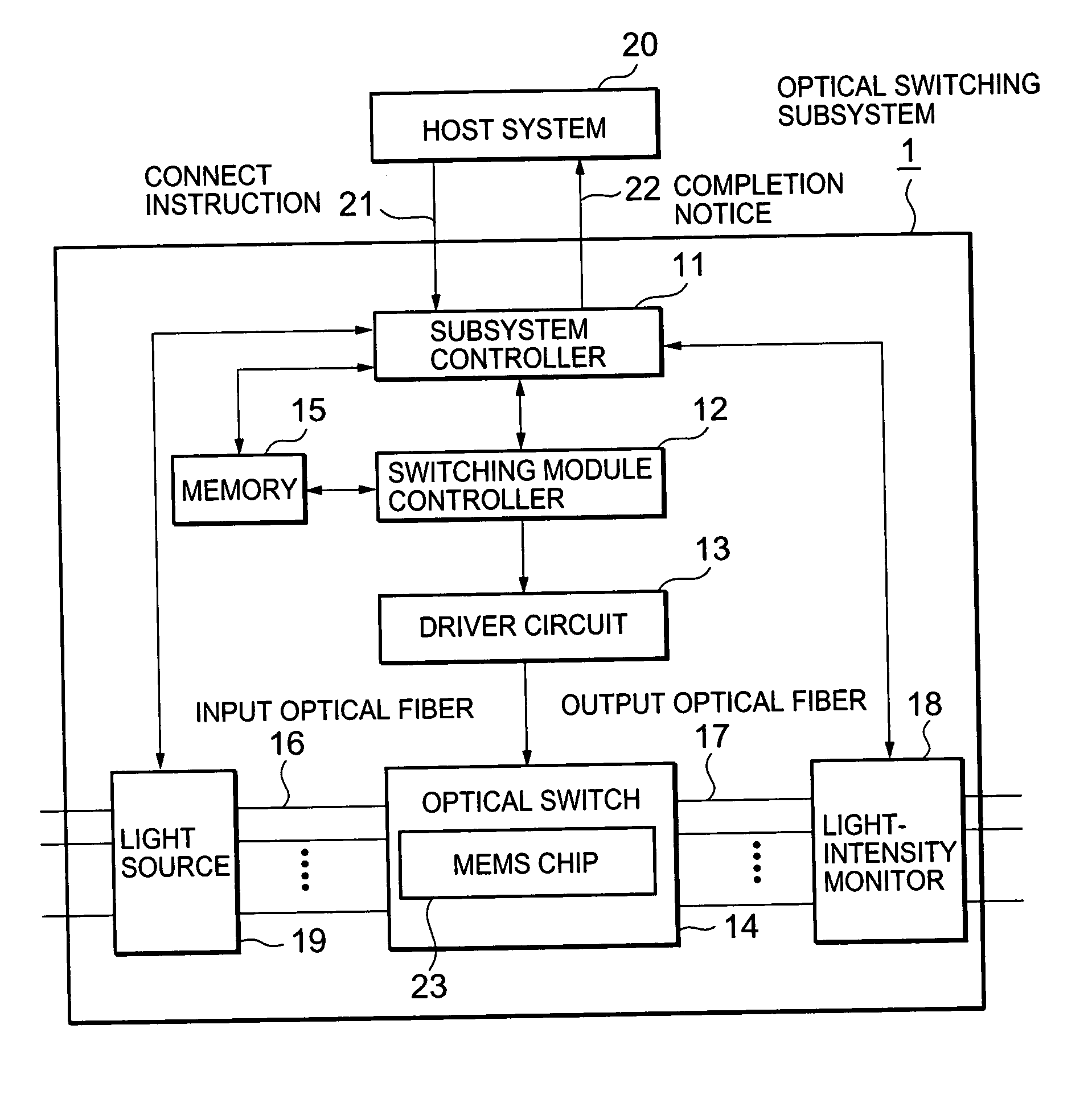
[0050] FIG. 1 is a block diagram showing the schematic configuration of an optical switching subsystem according to the first embodiment of the present invention.

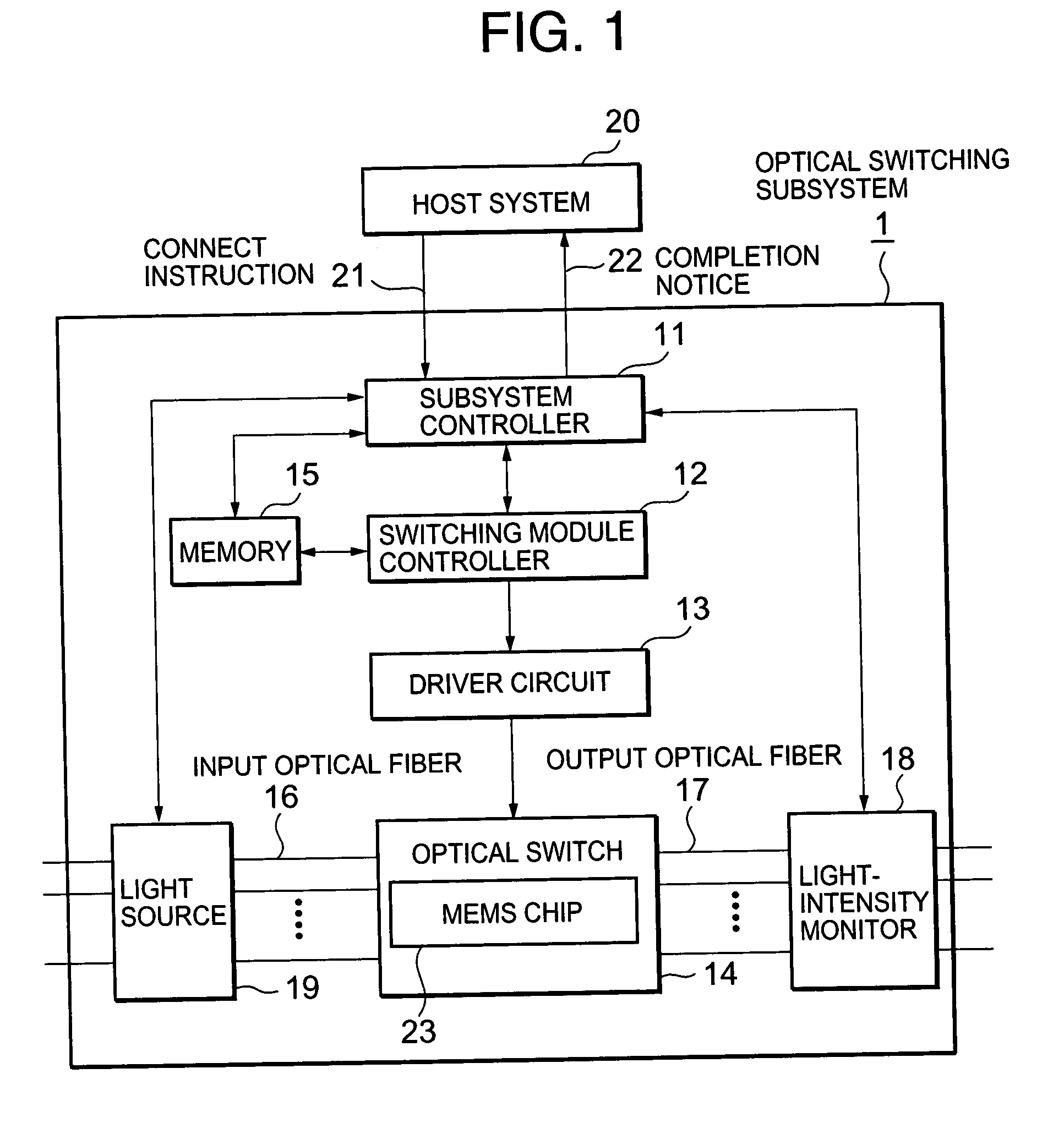
[0051] As shown in FIG. 1, the optical switching subsystem 1 is provided with a subsystem controller 11, a switching module controller 12, a driver circuit 13, an optical switch 14, a memory 15, an input optical fiber 16, an output optical fiber 17, a light-intensity monitor 18 and a light source 19.

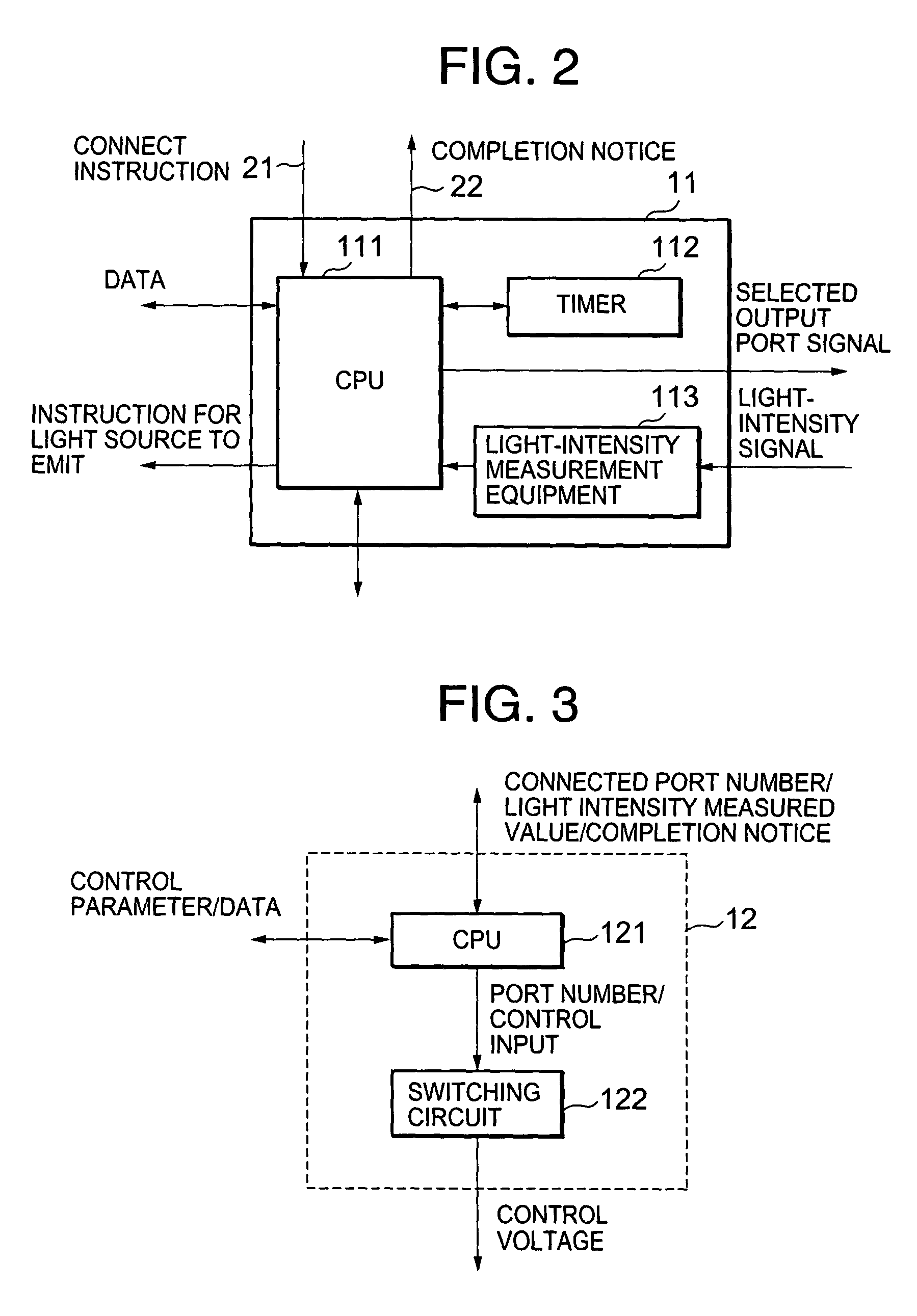
[0052] The subsystem controller 11 has an interface with a host system 20 and controls the whole optical switching subsystem 1. The switching module controller 12 controls the driving of a mirror in the optical switch 14 according to an instruction from the subsystem controller 11. The driver circuit 13 amplifies control voltage for driving the mirror output from the switching module controller 12 up to the voltage r...

second embodiment

[0117] [Second Embodiment]

[0118] Next, referring to FIGS. 10 and 11, a second embodiment of the invention will be described. However, the same reference number is allocated to a common component to the first embodiment and the detailed description is omitted.

[0119] FIG. 10 is a flowchart showing self-diagnosis operation (when an optical signal is communicated) in the second embodiment and FIG. 11 is a flowchart showing the judgment of rank in the self-diagnosis operation.

[0120] An optical switching subsystem 1 equivalent to the second embodiment is substantially the same as that in the first embodiment in view of the structure. However, the optical switching subsystem in the second embodiment is different from that in the first embodiment in that self-diagnosis operation is executed when an optical signal is communicated (the angle of a reflecting mirror is held).

[0121] When an optical signal is communicated, the optical switching subsystem 1 keeps input / output ports in a connected ...

third embodiment

[0134] [Third Embodiment]

[0135] Next, referring to FIG. 12, a third embodiment of the invention will be described. However, the same reference number is allocated to configuration common to that in each embodiment and the detailed description is omitted.

[0136] FIG. 12 is a block diagram showing the configuration of a feedback control system equivalent to the third embodiment.

[0137] The structure of an optical switching subsystem 1 equivalent to the third embodiment is substantially the same as that in the previous embodiments. However, the optical switching subsystem to the third embodiment is different from those in the embodiments in that calibration operation related to the control of an optical switch 14 is executed and self-diagnosis operation is executed based upon a correction value (a control input preset value) to be calibrated output from a controller.

[0138] In the third embodiment, calibration is executed when the subsystem is activated, every predetermined time or after ...


PUM


Abstract

An optical switching subsystem comprising; a plurality of input optical ports for inputting an optical signal, a plurality of output optical ports for outputting the optical signal, an optical switch formed by a micro electromechanical system (MEMS) for switching an optical path among said input optical ports and said output optical ports, a controller for instructing said optical switch to execute switching operation, and self-diagnosis means for measuring performance characteristics of said optical switching subsystem and diagnosing said optical switching subsystem based upon said performance characteristics.

Description

[0001] 1. Field of the Invention[0002] The present invention relates to an optical switching subsystem that switches an optical path in an optical communication system such as an optical fiber communication network, particularly relates to an optical switching subsystem formed by a micro electromechanical system (MEMS).[0003] 2. Description of the Related Art[0004] Recently, in an optical communication system represented by an optical fiber communication network, along with the increase in development of signal multiplexing technology, the need for an optical switch (an optical switching subsystem) that switches an optical path has increased.[0005] For example, in an optical fiber communication network according to wavelength division multiplexing (WDM), after a multiplexed optical signal is selectively branched at each node on the network, a path is switched using an optical switch.[0006] For the optical switch, multiple channels and a large scale are required to correspond the inc...

Claims


Application Information

Patent Timeline
Patent Type & Authority Applications(United States)
IPC IPC(8): G02B6/35G02B26/08H04B10/00H04B10/27H04Q11/00
CPCG02B6/3512G02B6/356G02B6/357H04Q2011/0083G02B6/359H04Q11/0005H04Q2011/0043G02B6/3586
Inventor OKUMURA, TOSHIYUKIYANAGITA, YOSHIHOYANAGIMACHI, SHIGEYUKI
Owner DENSO CORP
Why Eureka
Try Eureka