Method and device for monitoring and improving patient-ventilator interaction

a technology for monitoring and improving patient ventilation, applied in the direction of medical devices, valve details, operating means/releasing devices, etc., can solve the problems of increasing the ineffective effort, unable to completely trigger the ventilator, and often marked trigger delay, etc., to increase the trigger threshold and increase the uncertainty

Inactive Publication Date: 2004-03-18
YRT
View PDF8 Cites 128 Cited by
  • Summary
  • Abstract
  • Description
  • Claims
  • Application Information

AI Technical Summary

Benefits of technology

0130] As may be expected, when there are no errors (i.e. K.sub.v=E and K.sub.f.cent.K1, middle line, FIG. 4), signal Z is identical to the actual P.sub.mus waveform. However, when there are differences between assumed values and actual values, the baseline, prior to T.sub.onset is neither flat nor linear. When K.sub.v is >E, or K.sub.f is <K.sub.v (upper two lines), baseline is sloping down. Under these conditions, there is a qualitative change in direction of signal Z at T.sub.onset of effort. Such a directional change can be easily detected (e.g. by differentiating signal Z and looking for the point at which the differentiated signal becomes positive). However, when K.sub.v is <E, or K.sub.f is >K.sub.1 (bottom two lines, FIG. 4), baseline is sloping up and T.sub.0,s.sub.5t is evident as a change in slope; a quantitative, as opposed to the qualitative, difference observed with the opposite errors. To identify inspiratory effort under these con

Problems solved by technology

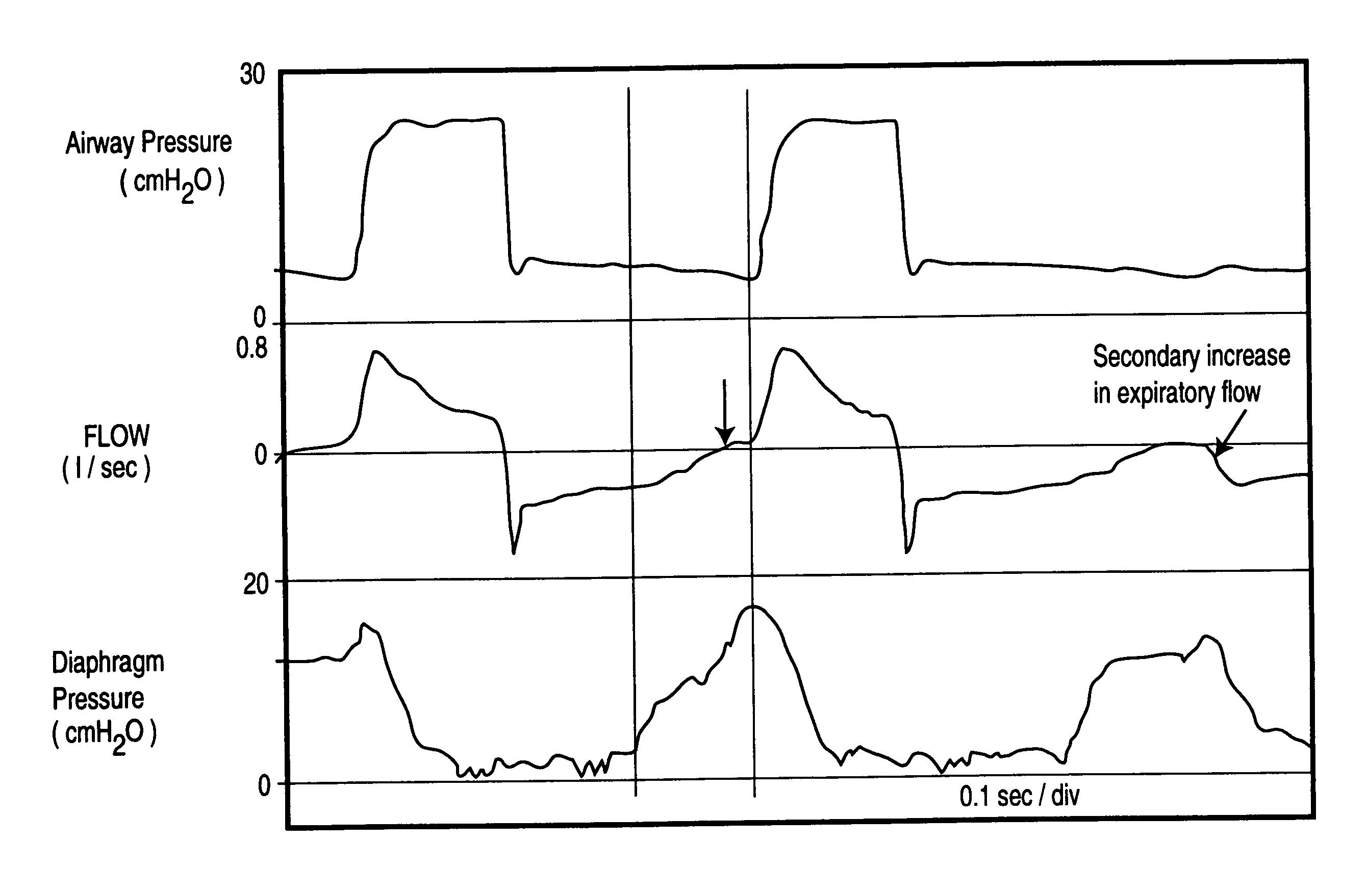
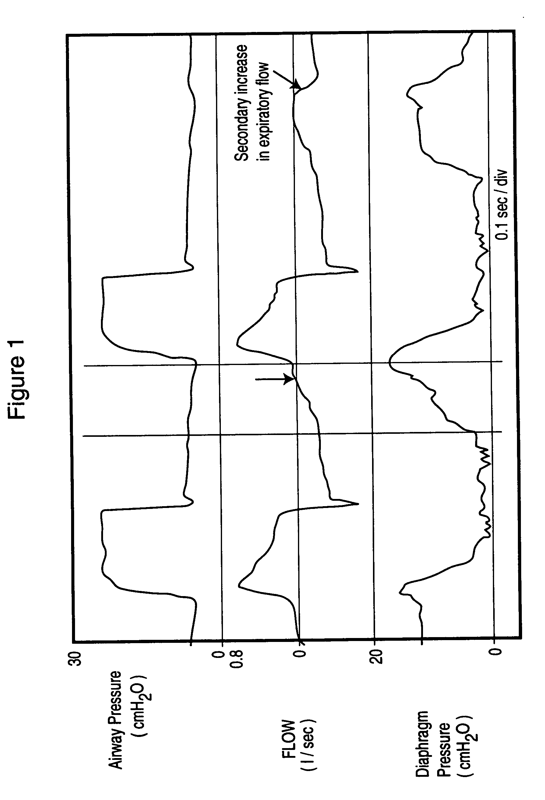
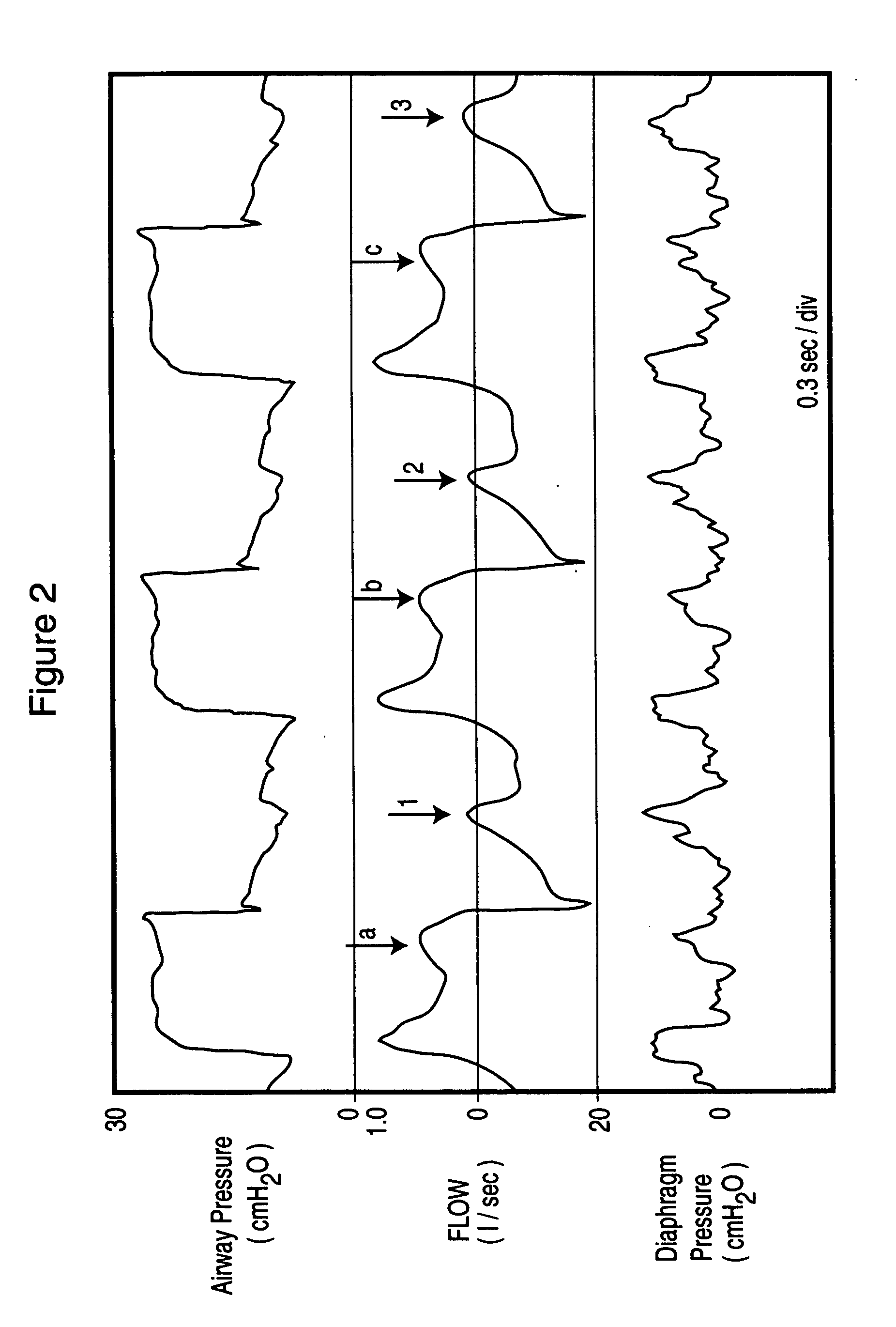
Trigger delay is often so marked that some efforts completely fail to trigger the ventilator (ineffective efforts, e.g. third effort, FIG. 1).
There are, accordingly, two inspiratory efforts within a single inflation phase and there is an additional ineffective effort during the ventilator's expiratory phase.
Non-synchrony is believed to cause distress, leading to excessive sedation and sleep disruption, as well as errors in clinical assessment of patients since the respiratory rate of the ventilator can be quite different from that of the patient.
Thus, if the response of the ventilator is poor, triggering may not occur immediately when the triggering criteria are reached.
This component of trigger delay can, however, still be excessive if the user sets an unnecessarily high threshold.
This setting may be because of lack of sufficient expertise, or because there was excessive baseline noise at some point, which necessitated a high threshold to avoid auto-triggering.
This delay is related to the fact that expiratory resistance is usually high in ventilated patients and expiratory time is frequently too short to allow lung volume to return to FRC (functional residual capacity) before the next effort begins.
Cycling-off errors result from the fact that, except with Proportional Assist Ventilation, current ventilator modes do not include any provision that links the end of ventilator cycle to end of the inspiratory effort of the patient.
While this method may yield reasonably accurate results in the intended application (treatment of obstructive sleep apnea patients with non-invasive BiPAP), a number of considerations suggest that its use in critically ill, intubated, ventilated patients may not provi

Method used


Image

  • Method and device for monitoring and improving patient-ventilator interaction
  • Method and device for monitoring and improving patient-ventilator interaction
  • Method and device for monitoring and improving patient-ventilator interaction

Examples


third embodiment

[0181] Certain internal signals need to be displayed to allow the user to adjust the input settings, while others provide the user with the results of monitoring. These signals can be displayed on a monitor 78 included in a freestanding device. Alternatively, if the device is incorporated inside the ventilator, the monitor of the ventilator can be used for this purpose. A third embodiment involves directing the device's outputs to an analog to digital converter and displaying the outputs on a separate computer.

[0182] The following output signals are necessary for adjusting the input settings:

[0183] a) The main signal itself 31.

[0184] b) The output of the integrator 48 in the T.sub.onset circuit (32).

[0185] The use of these two signals for the sake of input adjustment is described below under OPERATION (below).

[0186] Additionally, the signals representing flow 9, pressure 15 and volume 79 may be displayed on the monitor for general monitoring purposes.

[0187] Signals representing the ...

embodiment 103

[0189] In another embodiment of the output processor 103 patient respiratory rate (or T.sub.TOT) is inputted to the processor, replacing the "Calculate Patient Rate" function 83. This input is then used to calculate the "Desirable T.sub.1" 87 and "Flow at Desired T.sub.1" 90. Patient respiratory rate may be determined by the user from inspection of chest movements or by observing the flow tracing on the monitor, or automatically using computational methods other than the ones described in the above

Operation

[0190] When the device is built inside the ventilator, the pressure 15 and flow 9 signals are permanently connected to the device. For freestanding systems, the first step is to connect the flow meters and pressure ports to the inspiratory 2 and expiratory 3 lines close to the ventilator (FIG. 7). The device is turned on. Tracing of the Signal 31 appears on the screen (FIG. 10). Subsequent steps depend on what inputs are available on the device and user preference. For the most co...


PUM


Abstract

Method and apparatus for non-invasively determining the time onset (Tonset) and end (Tend) of patient inspiratory efforts. A composite pressure signal is generated comprising the sum of an airway pressure signal, a gas flow pressure signal obtained by applying a gain factor (Kf) to a signal representing gas flow rate and a gas volume pressure signal obtained by applying a gain factor (Kv) to a signal representing volume of gas flow. Kf and Kv values are adjusted to result in a desired linear trajectory of composite pressure signal baseline in the latter part of the exhalation phase. The current composite pressure signal is compared with (i) selected earlier composite pressure signal values and/or (ii) value expected at current time based on extrapolation of composite pressure signal trajectory at specified earlier times and/or (iii) the current rate of change in the composite pressure signal with a selected earlier rates of change. The differences obtained by the comparison are compared with selected threshold values. Tonset is identified when at least one of the differences exceeds the threshold values.

Description

REFERENCE TO RELATED APPLICATION[0001] This application claims priority under 35 USC 119(e) from U.S. Provisional Patent Application No. 60 / 391,594 filed Jun. 27, 2002.[0002] This invention relates to assisted mechanical ventilation.BACKGROUND TO THE INVENTION[0003] With assisted ventilation (e.g. assist volume cycled ventilation, pressure support ventilation and proportional assist ventilation) ventilator cycles are triggered by the patient and are intended to coincide with patient's inspiratory effort. In practice, however, the ventilator cycle never begins at the onset of patient's inspiratory effort (trigger delay) and the end of the ventilator's inflation phase only rarely coincides with the end of inspiratory effort (cycling-off errors). FIG. 1 provides an example. The bottom channel is transdiaphragmatic pressure (measured by esophageal and gastric catheters) and reflects' true patient inspiratory effort. As may be seen, ventilator cycle was triggered several hundred millisec...

Claims


Application Information

Patent Timeline
IPC IPC(8): A61M16/00
CPCA61M16/0051A61M2016/0021A61M2016/0042A61M2016/0039A61M2016/0027A61M16/026A61M2230/46
Inventor YOUNES, MAGDY
Owner YRT
Why Eureka
Try Eureka