Magnetic suspension system

a suspension system and magnetic technology, applied in the field of magnetic suspension systems, can solve the problems of less gap between the object and the structure than is theoretically possible, and it is impossible under normal circumstances to provide a magnetic suspension uni

Inactive Publication Date: 2004-03-18
IDENTIFIED FLYING OBJECTS
View PDF6 Cites 24 Cited by
  • Summary
  • Abstract
  • Description
  • Claims
  • Application Information

AI Technical Summary

Benefits of technology

0019] FIG. 7 is a block diagram representation of the control circuit for magnetic suspension.
0020] FIG. 8 is a blo...

Problems solved by technology

However, the gap between the object and the structure is less than is theoretically possible.
It is impractical under normal circumstances to ...

Method used


Image

  • Magnetic suspension system
  • Magnetic suspension system
  • Magnetic suspension system

Examples


Embodiment Construction

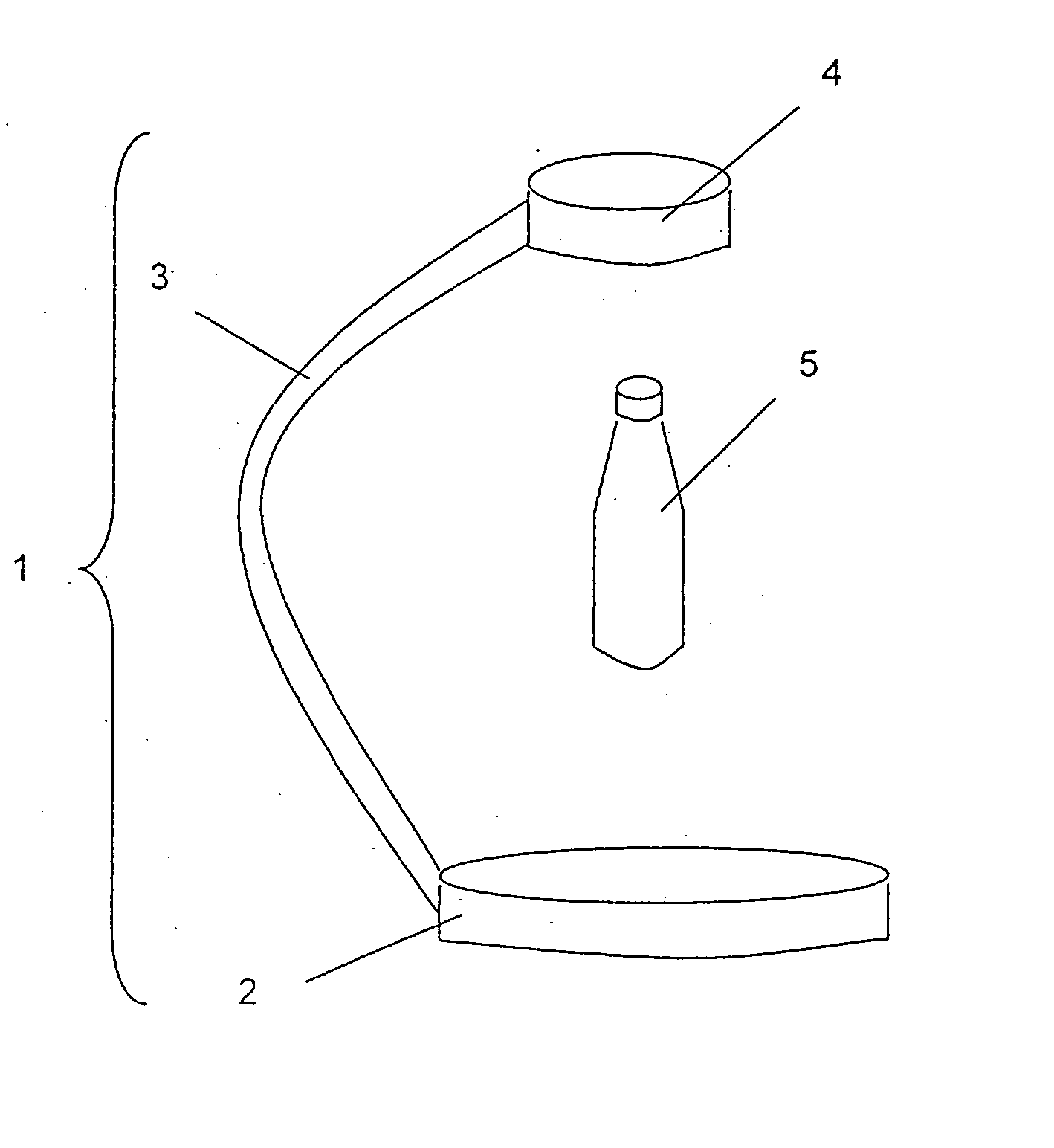
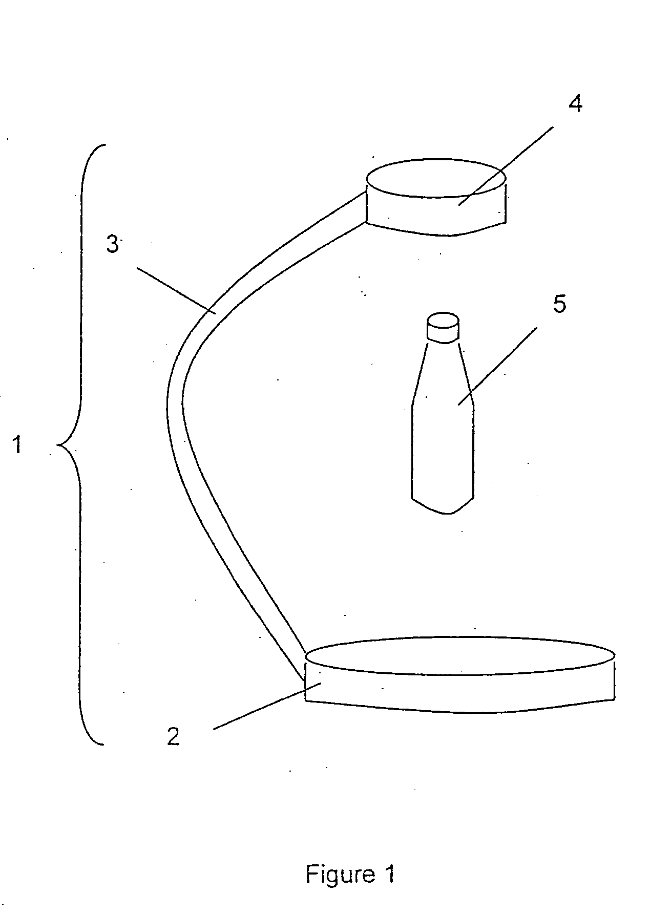
[0021] FIG. 1 shows a typical manifestation of a magnetic suspension device. The frame (1) is divided into a stand (2), an arm (3) and a head unit (4). These may be constructed integrally or from several joined components. The object (5) is suspended below the head unit.

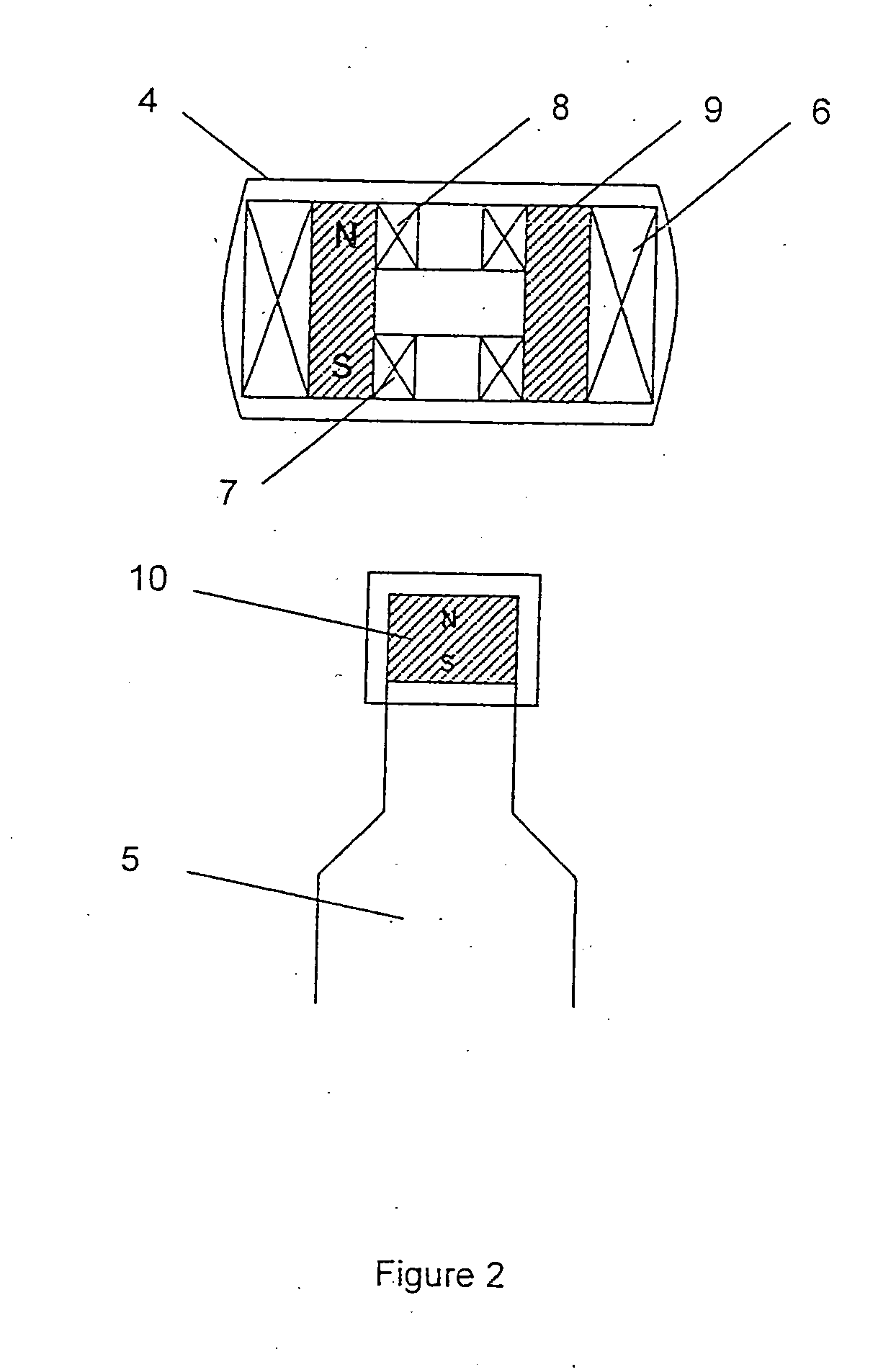
[0022] FIG. 2 is a cross section of an embodiment of the unit demonstrated in FIG. 1. Inside the head unit (4) is an air core electromagnet (6) which is controlled by a power application circuit which will be described later. A first permanent magnet (9) is mounted within the inner diameter of the electromagnet. Two magnetic field sensor coils (7) and (8) are mounted within the inner diameter of the permanent magnet (9) which in this example is of the ring or "doughnut" type. The windings of the electromagnet and the two sensor coils are coaxial and the axis of magnetization of the permanent magnet is substantially vertical.

[0023] The choice of ring geometry for the head unit permanent magnet (9) results in a passive...


PUM


Abstract

Systems are disclosed for holding an object in mid-air under the influence of fixed and variable magnetic forces countering the gravitational pull of the object. These systems can be used for display purposes, such as advertising or commercial displays; and/or educational purposes such as spinning globes. It is perceived that the larger the gap between the suspended object and the structure containing the magnets and control systems, the more desirable the device becomes.

Description

[0001] The current invention is a system for holding an object in mid-air under the influence of fixed and variable magnetic forces countering the gravitational pull on the object.[0002] Such systems can be used for display purposes such as advertising or commercial displays; and / or educational purposes such as spinning globes.[0003] It is perceived that the larger the gap between the suspended object and the structure containing the magnets and control systems, the more desirable the device becomes.[0004] Such a systems has been disclosed in U.S. Pat. No. 6,154,353 whereby a fixed support has an upper station containing a permanent magnet, an electromagnet and a sensor system. The suspended object also has a permanent magnet and floats, below the upper station of the support frame. The permanent magnets are configured so as to attract one another in an upwards direction, countering the downwards gravitational force on the object. Hence a theoretical balance point is defined whereby...

Claims


Application Information

Patent Timeline
IPC IPC(8): H02N15/00
CPCH02N15/00
Inventor JOACHIM, GABRIEL LOUIS
Owner IDENTIFIED FLYING OBJECTS
Why Eureka
Try Eureka