Method for measuring the temperature of a metal saucepan

Inactive Publication Date: 2004-03-18
E G O ELEKTRO GERAETEBAU GMBH
View PDF9 Cites 22 Cited by
  • Summary
  • Abstract
  • Description
  • Claims
  • Application Information

AI Technical Summary

Problems solved by technology

However, for this it is necessary to calibrate in complicated manner the system in order to provide relatively accurate temperature information and this is looked upon as disadvantageous.

Method used


Image

  • Method for measuring the temperature of a metal saucepan
  • Method for measuring the temperature of a metal saucepan
  • Method for measuring the temperature of a metal saucepan

Examples


Embodiment Construction

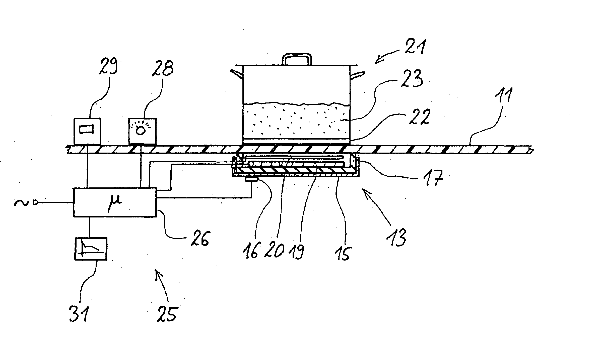
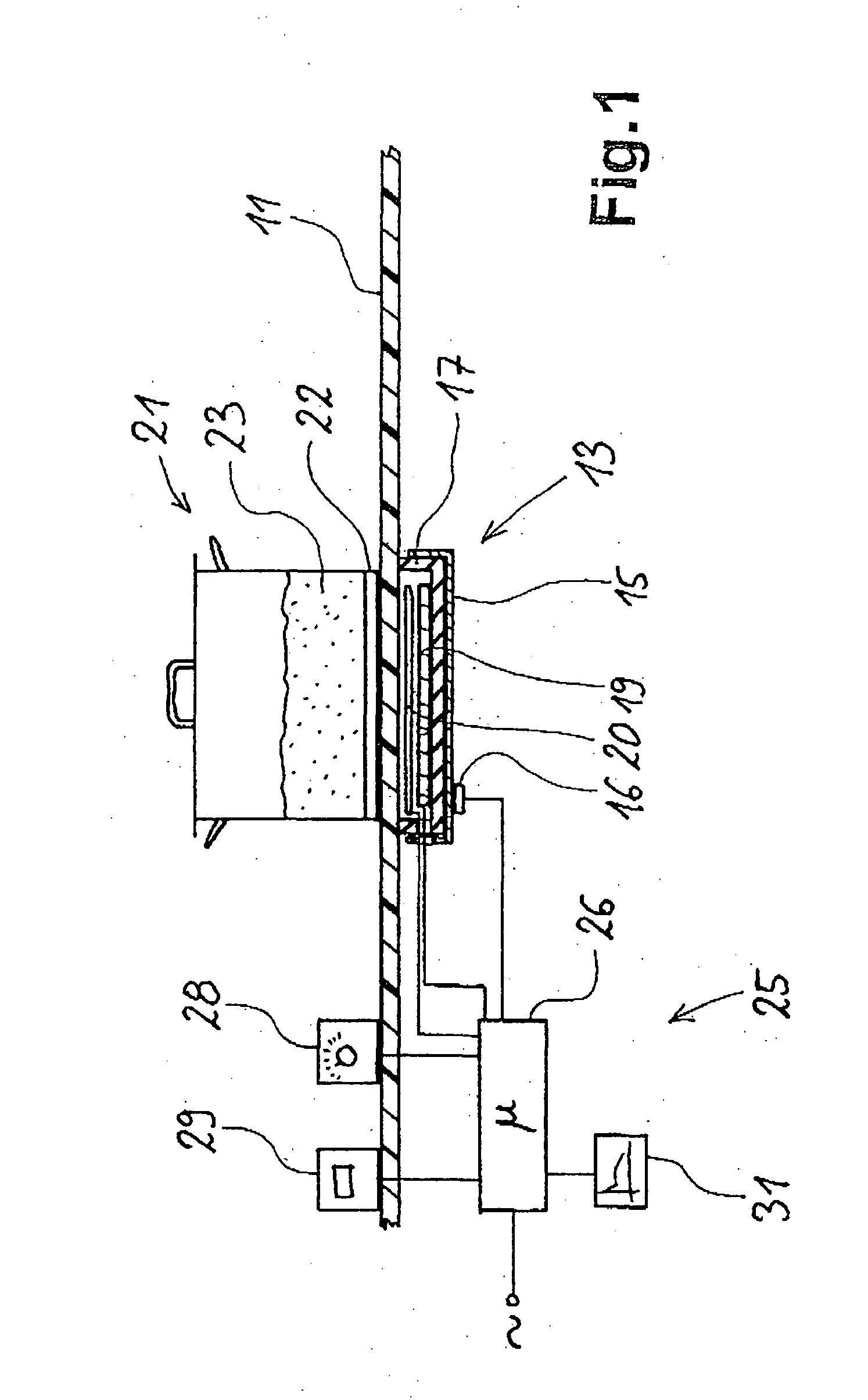
[0025] The diagrammatic FIG. 1 shows a glass ceramic cooking area 11. Below a hot point of the glass ceramic cooking area 11 is located a radiant heater 13, which is in principle constructed in known manner. In a sheet metal dish or tray 15 is inserted a flat, also dish or tray-shaped insulator 17, on which is located a heating coil 19. It is also possible to embed a heating coil 19 in the insulator 17. From below the radiant heater 13 is pressed onto the underside of the glass ceramic cooking area 11, which can e.g. take place by not shown retaining means.

[0026] Directly above the heating coil 19 is provided an induction coil 20 which, as described, can have a differing construction and can e.g. have a single turn.

[0027] Above the radiant heater 13 a cooking vessel or saucepan 21 is placed on the glass ceramic cooking area 11. By means of the radiant heater 13 energy is coupled into the saucepan bottom 22, which for this purpose has a ferromagnetic construction. As a result of the ...


PUM

PropertyMeasurementUnit
temperatureaaaaaaaaaa
frequenciesaaaaaaaaaa
temperatureaaaaaaaaaa

Abstract

A method for measuring the temperature of a cooking vessel or saucepan by means of a radiant heater is described. The radiant heater has a heating coil with a corresponding control and an induction coil as an inductive sensor and which is located in a metal tray. With the inductive sensor, measurement takes place of the frequency of the inductive resonant circuit comprising saucepan, heating coil, induction coil and metal tray, which is dependent on the temperature of the components. In the control is stored known slopes or paths of the temperature and therefore the frequency of the metal tray over the time. From this the control means gathers correction values in order to produce from the measured curve a compensated curve. At characteristic points, such as the start of a cooking or boiling process or an empty cooking or boiling of the saucepan, it is possible to detect said temperatures.

Description

FIELD OF APPLICATION AND PRIOR ART[0001] The invention relates to a method for measuring the temperature of a metal cooking vessel or saucepan in the vicinity of a heater and to an electrical heating device with temperature measurement.[0002] Methods and heaters provided with suitable devices for measuring the temperature of a metal saucepan are known in numerous different forms. In order to measure the temperature of a saucepan in non-contacting manner and to derive a temperature control therefrom, an attempt has e.g. been made to form a resonant circuit from an induction coil together with the metal saucepan bottom. This e.g. makes it possible to establish the resonant circuit frequency of the saucepan bottom. The latter is in turn determined by the temperature-dependent permeability of the saucepan bottom material. Therefore conclusions can be drawn concerning its temperature from the behaviour of the saucepan bottom. However, for this it is necessary to calibrate in complicated ...

Claims


Application Information

Patent Timeline
Patent Type & Authority Applications(United States)
IPC IPC(8): G05D23/20
CPCG05D23/2015G05D23/1917G05D23/20
Inventor SCHILLING, WILFRIEDBELLM, MATHIAS
Owner E G O ELEKTRO GERAETEBAU GMBH
Why Eureka
Try Eureka