Hand-held saber saw

Inactive Publication Date: 2004-03-25
ROBERT BOSCH GMBH
View PDF0 Cites 2 Cited by
  • Summary
  • Abstract
  • Description
  • Claims
  • Application Information

AI Technical Summary

Problems solved by technology

This coupling is relatively inelastic and is therefore vulnerable

Method used


Image

  • Hand-held saber saw
  • Hand-held saber saw
  • Hand-held saber saw

Examples


Embodiment Construction

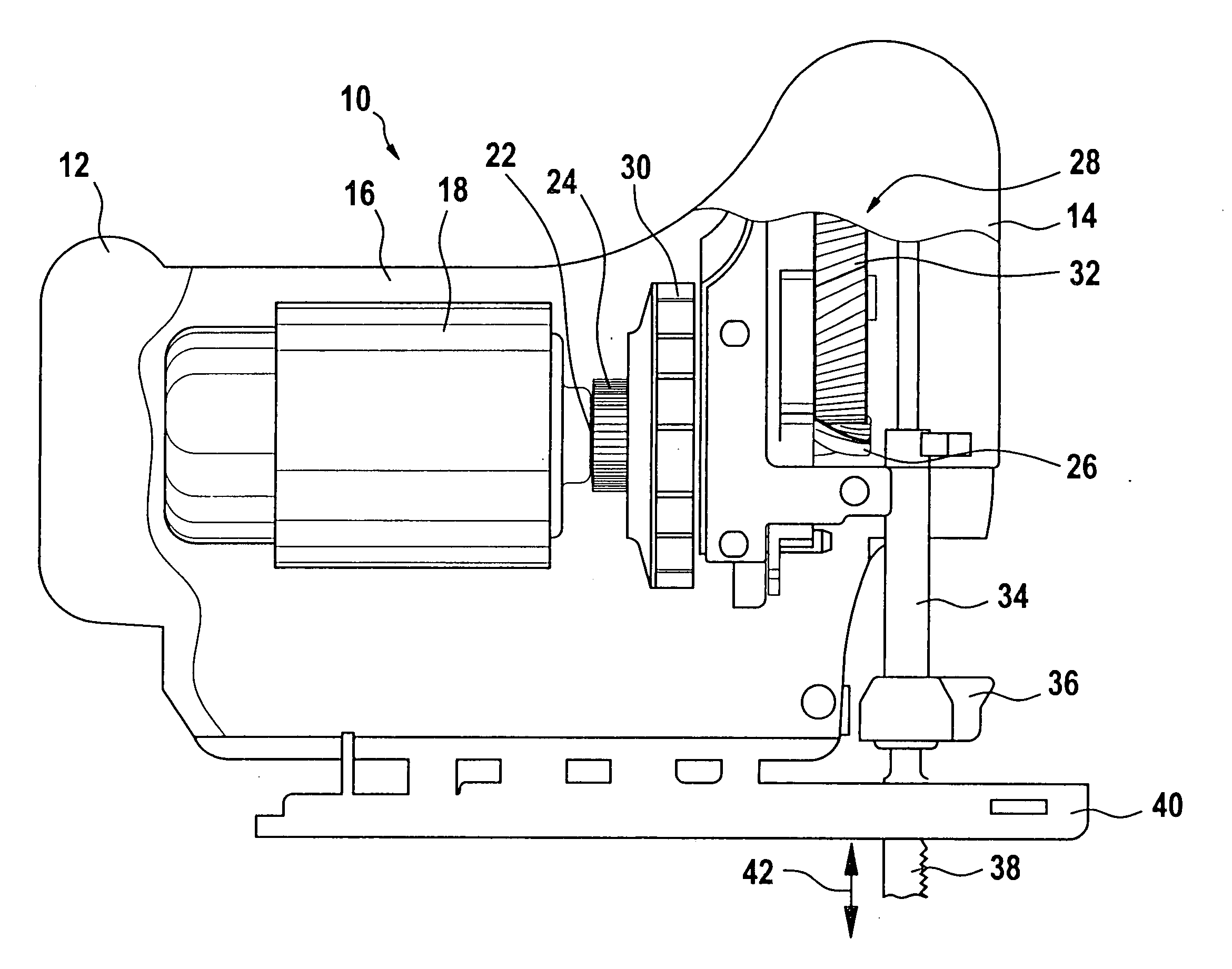
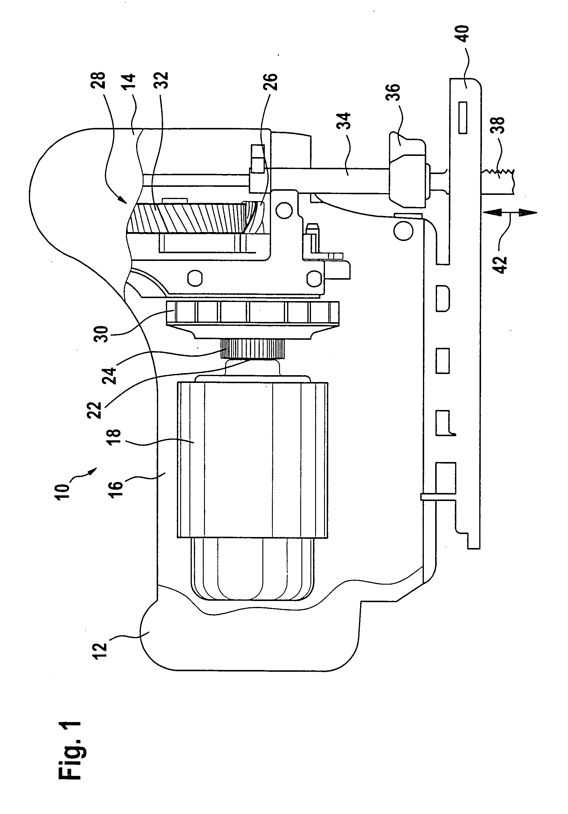
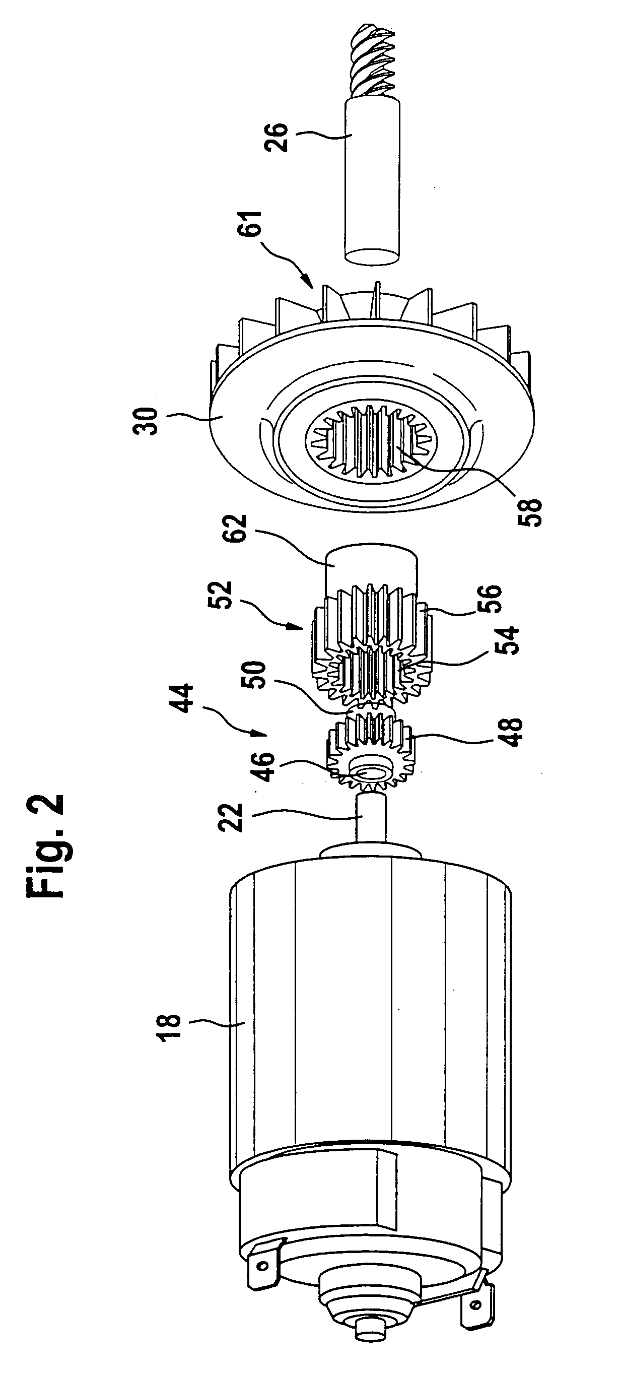
[0015] The power tool shown in FIG. 1 is designed a reciprocating hand saw 10, which can be supplied with energy via a battery pack 12 or direct current. It comprises a gearbox 14, to which a motor housing 16 is flanged. The motor housing 16, on its end, has a battery pack 12, and closely adjacent to the battery pack, a direct-current motor 18, mounted with vibration damping, whose motor shaft is coupled on the shaft end 22, via a multi-part coupling 24, to a gear input pinion 26 of a conventional reciprocating saw gear 28.

[0016] The coupling 24 has a fan 30, which serves to cool the motor or create blowing air to blow away chips that collects on the surface of workpieces as they are being sawed and make it more difficult to control the sawing process.

[0017] The reciprocating saw gear 28 comprises a large power takeoff pinion 32, whose rotary motion is converted, by a sliding block gear, not shown, into an up-and-down motion of a push rod 34 pointing downward out of the gearbox 14. ...


PUM

PropertyMeasurementUnit
Angleaaaaaaaaaa
Diameteraaaaaaaaaa

Abstract

A reciprocating hand saw (10), having a motor housing (16) and a gearbox (28) that receive a battery-operated direct-current motor (18) with a motor shaft having a shaft end (22) and a gear (28), respectively, which gear-as known per se in reciprocating saws-is connected to the shaft end in a way driven to rotate and whose gear input pinion (26) converts the rotation of the motor shaft end (22) into an up-and-down motion of a push rod (34) that carries a sawblade (38), can be produced economically and is especially sturdy because the gear (28) and its gearbox (14) originate in a reciprocating saw that can be operated by alternating current, and because between the shaft end (22) and the gear input pinion (26), a multi-stage coupling (24), disposed in a manner fixed against relative rotation for transmitting torque, comprises parts that can be easily separated from one another.

Description

PRIOR ART[0001] The invention is based on a reciprocating hand saw with a direct-current motor as generically defined by the preamble to claim 1.[0002] A reciprocating hand saw with a direct-current motor is already known in which the gearbox and the gear of a conventional reciprocating hand saw, which can be operated with alternating current, is coupled to a direct-current motor, and the gear input pinion is coupled in a manner fixed against relative rotation to the motor shaft of the direct-current motor via a one-piece coupling part. This coupling is relatively inelastic and is therefore vulnerable to a deviation in parallelism of the motor axis to the gear axis. Because of the requisite high alignment accuracy required, the known battery-operated reciprocating hand saw is relatively inexpensive and vulnerable to shock or impact, or in other words to an unwanted change in position of the motor.ADVANTAGES OF THE INVENTION[0003] The reciprocating hand saw of the invention with a di...

Claims


Application Information

Patent Timeline
IPC IPC(8): B23D49/16B23D51/16
CPCB23D49/16Y10S30/01B23D51/16B23D49/162
Inventor ZEITER, OLIVIERSAEGESSER, DANIEL
Owner ROBERT BOSCH GMBH
Why Eureka
Try Eureka