Canonical general response bandpass microwave filter

a microwave filter and general response technology, applied in waveguide type devices, basic electric elements, resonators, etc., can solve the problems of distortion, increase the mechanical complexity and number of filter elements, and prevent the filter from meeting the prescribed specifications of flat insertion loss, so as to reduce the number of mechanical components and reduce the distortion

Active Publication Date: 2004-03-25
ALCATEL LUCENT SAS
View PDF11 Cites 32 Cited by
  • Summary
  • Abstract
  • Description
  • Claims
  • Application Information

AI Technical Summary

Benefits of technology

0015] By using this invention the distortions are minimised and no diagonal cross couplings are needed in order to implement a symmetrical response.
0016] Furthermore, the invention allows the placement of some cross couplings between the i.sup.th and (i+z).sup.th resonators for 1.ltoreq.i.ltoreq.n-z, z being an odd number. Such cross couplings have higher values and therefore they are easily and accurately electrically characterized, thus. less critical in terms of design, manufacturing and temperature dependence. This means a less costly filter with easier tuning and more stable performances over a wide temperature range.

Problems solved by technology

However, these known microwave filter suffer from various disadvantages such as a distortion appearing in the response that leads to an asymmetric response.
This distortion prevents the filter meeting the prescribed specifications of flat insertion losses and linear phase.
Diagonal cross couplings are difficult to characterise, manufacture and tune and they increase the mechanical complexity and number of elements of the filter, thus raising the cost of the filter.
Moreover, cross couplings between non-sequential adjacent cavities are very low in magnitude for high order filters, leading to a difficult electrical characterisation procedure, a complex manufacturing and tuning, and worse performances in temperature.

Method used


Image

  • Canonical general response bandpass microwave filter
  • Canonical general response bandpass microwave filter
  • Canonical general response bandpass microwave filter

Examples


Embodiment Construction

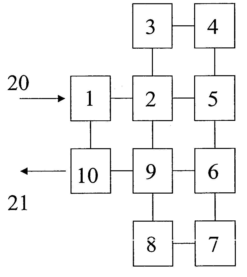
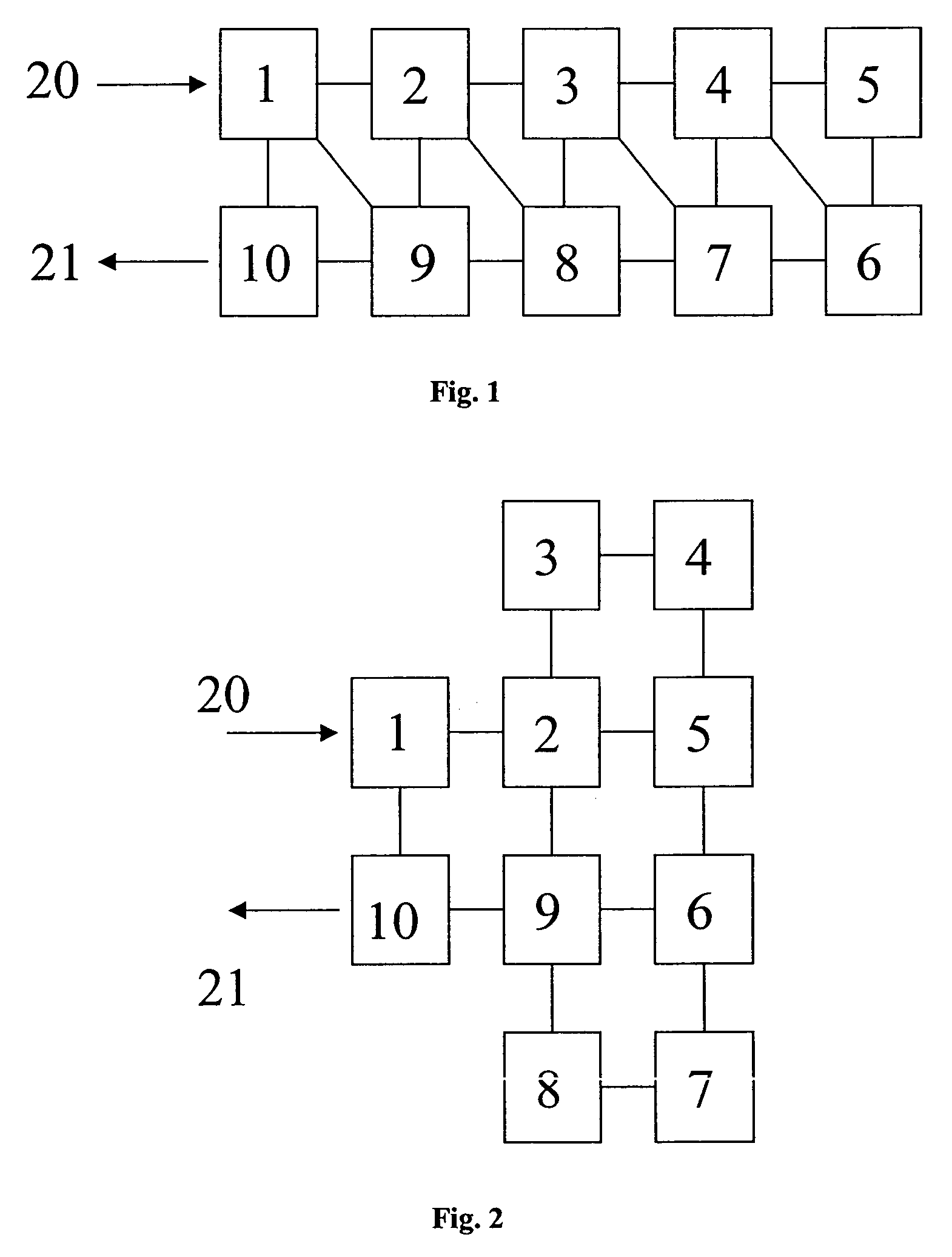
[0023] FIG. 1 depicts a single mode dielectric resonator microwave filter whose housing is provided with an input terminal 20 and an output terminal 21 connected respectively to a resonator cavity, such that each resonator cavity defines a row. The filter housing has several resonator cavities arranged in two rows.

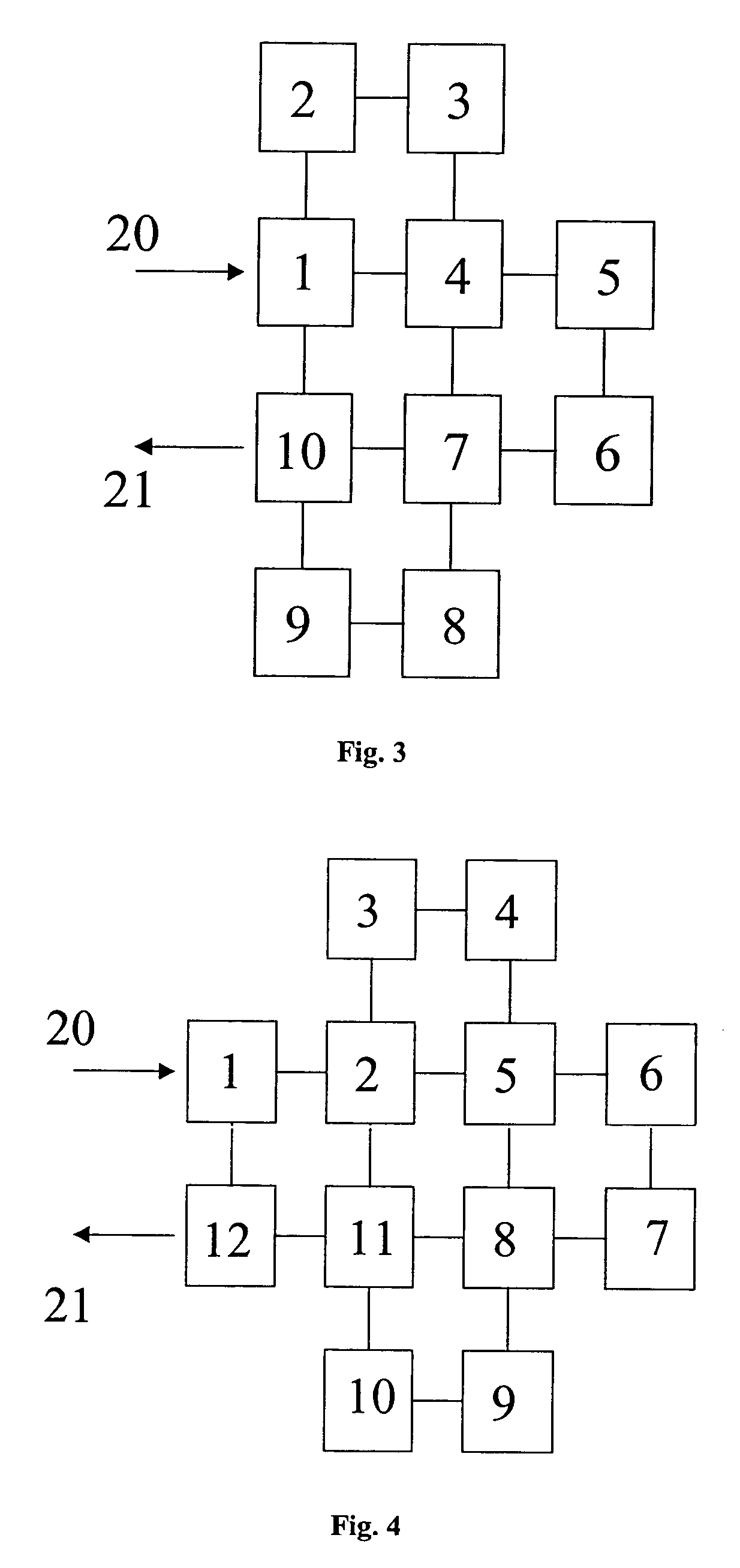
[0024] As to FIG. 2, a microwave filter is described according to the invention wherein the resonator cavities are arranged in several rows and several columns, that is, the resonator cavities define more than two rows and columns.

[0025] The first cavity 1 is connected to the filter input 20 which is non-sequential adjacent to a cavity 10 connected to the filter output 21. A resonator (not shown) is arranged within each resonator cavity such that the dielectric resonators are coupled one to another by means of an iris in the wall that separates one cavity from another.

[0026] A resonator cavity may be coupled to another resonator cavity and / or to several resonator cavities....


PUM


Abstract

A microwave filter comprising a plurality of resonator cavities (1, 10) arrangement in more than two adjacent rows and more than two adjacent colunms; each resonator cavity is coupled with at least a sequential adjacent resonator cavity for providing a main path for an electromagnetic energy to be transmitted from a first resonator cavity (1) to a last resonator cavity (10). The electromagnetic energy is injected in the first resonator cavity (1) by an input terminal (20) through an input coupling and the electromagnetic energy is extracted from the last resonator cavity (10) by an output terminal (21) through an output coupling, the first (1) and last (10) resonator cavities are non-sequential adjacent cavities.

Description

OBJECT OF THE INVENTION[0001] The present invention relates generally to microwave filters, and more particularly, to general response bandpass microwave filters for use in transmitters and receivers for communication satellite and wireless communication systems.STATE OF THE ART[0002] Canonical topology for bandpass filters are known to provide general responses both symmetrical and asymmetrical, with the maximum number of finite zeros for a given number of resonators, thus allowing sharp selectivity and linear phase responses to be implemented.[0003] One canonical single mode multi-cavity microwave filter is described in U.S. Pat No. 5,608,363 to Cameron et al. wherein there is a multi-cavity housing formed with a plurality of walls defining a plurality of cavities, that are sequentially arranged in first and second side-by-side rows, each row having a plurality of cavities.[0004] The filter housing has an input and an output such that an input device is arranged adjacent to and co...

Claims


Application Information

Patent Timeline
Patent Type & Authority Applications(United States)
IPC IPC(8): H01P1/207H01P1/20H01P1/205H01P1/208H01P7/10
CPCH01P1/2053H01P1/2084H01P1/208
Inventor CARPINTERO, ISIDRO HIDALGOCRUANES, ELVIRA CERVERACRUZ, MANUEL JESUS PADILLA
Owner ALCATEL LUCENT SAS
Why Eureka
Try Eureka