Concrete forming panel having built-in retaining structure for storing loose coupling parts

Inactive Publication Date: 2004-04-15
WESTERN FORMS
View PDF20 Cites 6 Cited by
  • Summary
  • Abstract
  • Description
  • Claims
  • Application Information

AI Technical Summary

Benefits of technology

0007] These problems have largely been solved by the panel of the present invention. By having parts-holding structure built into the form itself, the parts are always conveniently available for use. Moreover, by having the parts retaining structure spaced from the coupling sites and disposed s

Problems solved by technology

However, keeping track of the large number of pins, wedges, nuts and other connectors has been a problem.
One other problem associated with such small parts is that they are often not readily available to the workman who must assemble the forms.
Thus, parts may be lost or displaced, located in a remote area on the jobsite, or otherwise separated from the forming panel.
Certain parts are relatively specialized and thus somewhat expensive to replace, and are repeatedly used with the same forming panel.
Moreover, several workman must often wait while the parts are obtained by another workman, resulting in the loss of productive time of not merely one but several workers.
Thus, the expensive of replacement parts and the time lost in locating and retrieving such small parts is an economic loss as well as an aggravation to the construction crew.
While the forming panels include a plurality of coupling sites which are normally adapted to receive some or all of the parts for use in, for exam

Method used


Image

  • Concrete forming panel having built-in retaining structure for storing loose coupling parts
  • Concrete forming panel having built-in retaining structure for storing loose coupling parts
  • Concrete forming panel having built-in retaining structure for storing loose coupling parts

Examples


Example

. 1-8

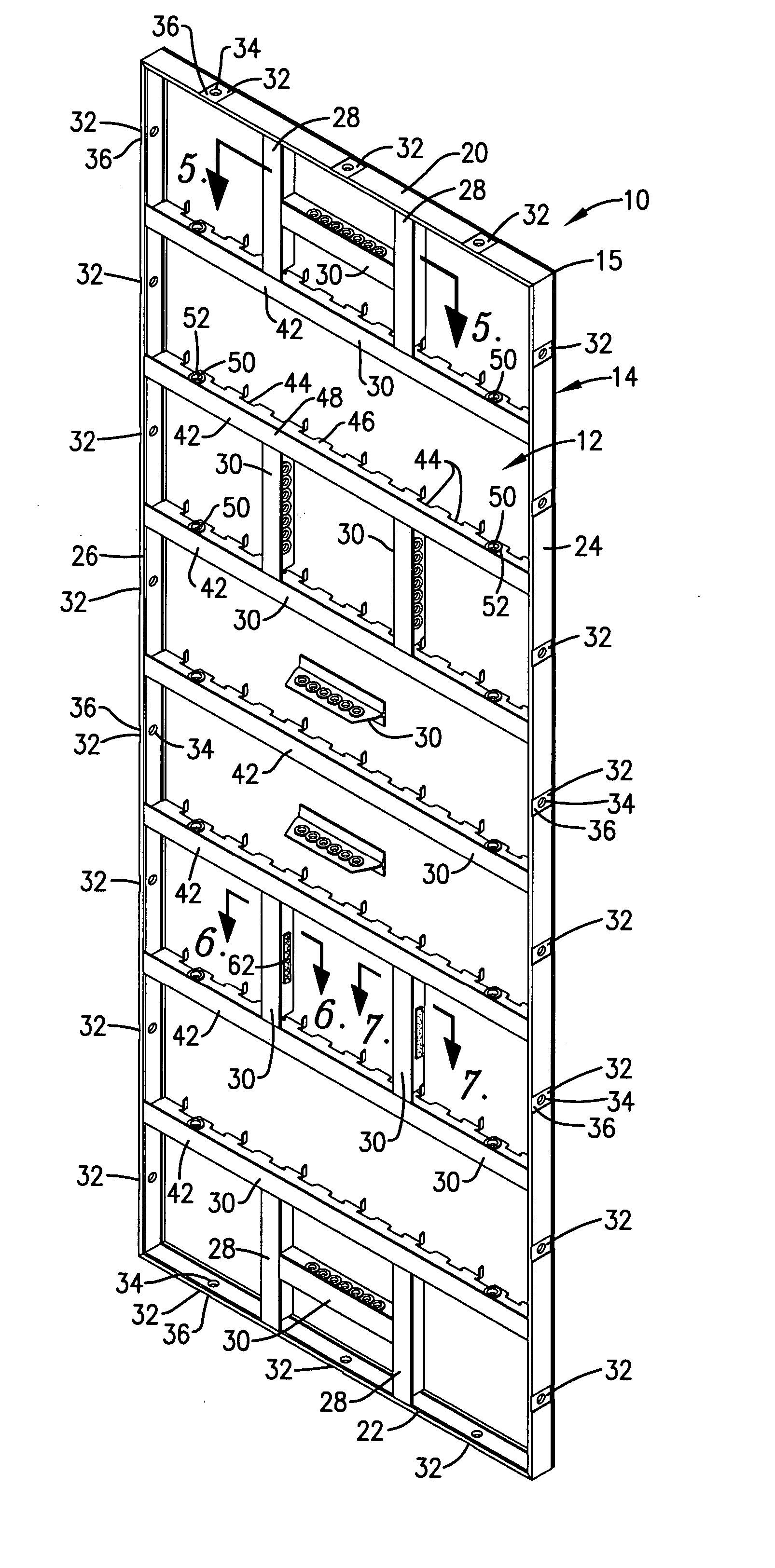
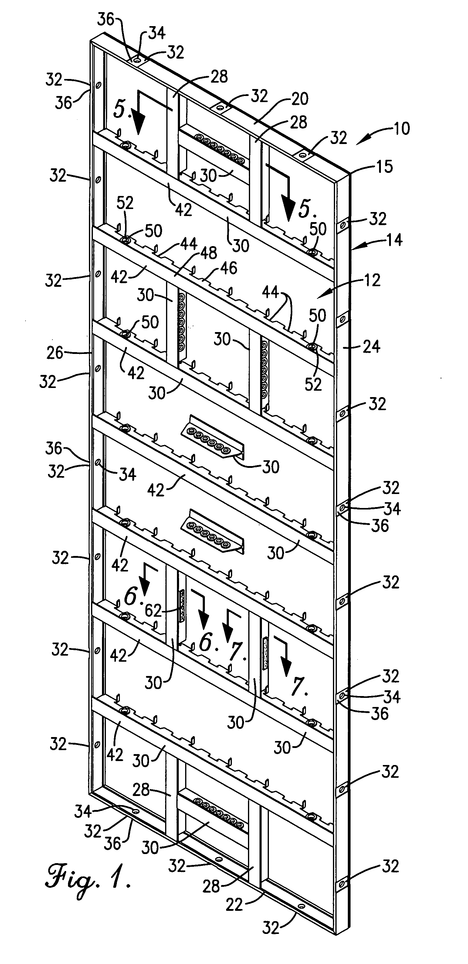
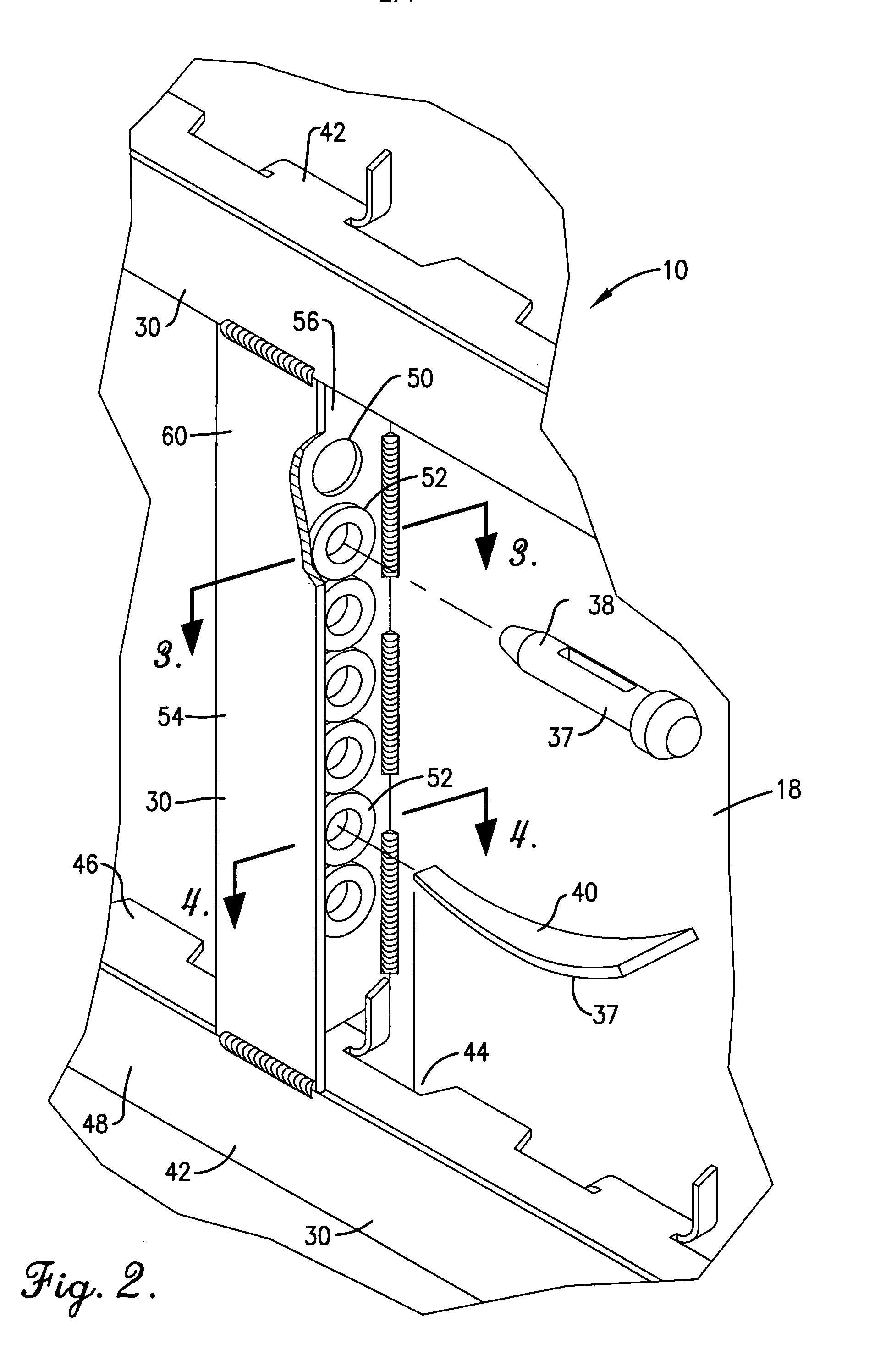
[0024] Referring now to the drawings, a forming panel 10 for receiving flowable concrete there against and providing a form for hardening the concrete to a desired shape is generally shown in FIG. 1 and includes a face sheet 12 and a frame 14. The face sheet and frame are provided preferably primarily of aluminum, to include alloys thereof such as ASTM 6061-T6. The face sheet 12 is relatively thin, for example about 0.090 to 0.125 for lightweight applications but may be made thicker for heavier duty applications, and may be substantially flat or textured to provide a brickface or other texture to the concrete hardening thereagainst. The face sheet 12 includes a perimeter 15, a front side 16 and a back side 18, and is welded to the frame 14.

[0025] The frame 14 has at least one rail of a thickness typically varying between 0.125" and 3 / 8" for lightweight applications, with thicker aluminum stock provided for larger sizes and heavier duty applications if desired. The frame 14 may ...


PUM


Abstract

A concrete forming panel has built-in retaining structure for holding loose coupling parts in a safe, secure position when the parts are stored during times of nonuse of the panel. Members on the backside of the face plate of the panel, including but not necessarily limited to bracing or stiffening members of the frame, are provided with webs or wall portions having a series of clearance openings therein. Brush rings are positioned immediately adjacent each opening and have radially inwardly directed resilient bristles that terminate in innermost ends defining a hole aligned with the adjacent opening. Consequently, when a oversized coupling part relative to the brush hole is inserted into such hole, it flexes the bristles and passes through the hole and the adjacent opening in the supporting member to be retained in place in a yieldable, releasable manner by the flexed bristles. In a preferred embodiment, the brush rings are retained in place frictionally on each member by a wedging action between the brush rings and a receiving track on the side of the wall of the member.

Description

[0001] This application is a continuation-in-part of prior co-pending application Ser. No. 09 / 791,399 filed Feb. 23, 2001 titled Method and Apparatus for Retaining Separable Coupling Parts for Concrete Forming Panel.[0002] This invention relates to concrete forming panels and, more particularly, to a concrete forming panel that is provided with built-in structure for safely and securely retaining and storing separate, loose coupling parts which may be used in connecting the forming panel with other panels to make a form.BACKGROUND OF INVENTION[0003] Forming panels used in erecting concrete walls for structures are often provided in standard sizes and shapes, and thus must be connected in order to establish a pair of opposed forming walls into which concrete may be poured for hardening into the final structural shape. Thus, adjacent forming panels are coupled together by pins, wedges and other fasteners, and opposing walls are connected by tie bars and the like. The purpose of such f...

Claims


Application Information

Patent Timeline
IPC IPC(8): E04G17/04
CPCE04G17/045E04G17/04
Inventor WARD, PHILIP T.
Owner WESTERN FORMS
Why Eureka
Try Eureka