Energy-saving and wind-powered aerator

a technology of aerators and wind turbines, which is applied in the field of aerators, can solve the problems of increasing the production cost of aquaculture industry, insufficient oxygen dissolved in water, and high electricity fees, so as to reduce the amount of electricity consumed in the aquaculture industry, increase the amount of oxygen dissolved in water, and improve the effect of water quality

Inactive Publication Date: 2010-12-23
JETPRO TECH
View PDF16 Cites 17 Cited by
  • Summary
  • Abstract
  • Description
  • Claims
  • Application Information

AI Technical Summary

Benefits of technology

[0008]With this arrangement, natural wind can be used as the power for rotating the wind turbine. The transmission element transmits the rotating energy of the wind turbine to drive the water stirrer to beat water rapidly, thereby increasing the amount of oxygen dissolved in water. In this way, organic compounds can be decomposed in the water to improve the water quality. Since the natural wind is inexhaustible in supply and always available for use, using wind as the power for the aerator, the amount of electricity consumed in aquaculture industry can be reduced to increase its profit. The fuels consumed by a power plant for generating electricity can be also reduced to conserve the resources in the earth. The present invention is simple in structure, easy to manufacture, low in price, effective in converting the wind power into a force for stirring water, and excellent in economical benefit. Further, the wind turbine can be automatically adjusted to the wind direction to utilize the wind power more efficiently.

Problems solved by technology

However, when the external air is merely brought into direct contact with the water surface, the amount of oxygen dissolved in the water is insufficient.
In any event, the amount of electricity consumed by the aerator is large after a long period of use, so that the high electricity fee increases the production cost of the aquaculture industry.

Method used


Image

  • Energy-saving and wind-powered aerator
  • Energy-saving and wind-powered aerator
  • Energy-saving and wind-powered aerator

Examples


Embodiment Construction

[0016]The detailed description and technical contents of the present invention will be explained in more detail with reference to an preferred embodiment thereof shown in the accompanying drawings. However, it should be understood that the drawings are illustrative only, but not used to limit the scope of the present invention.

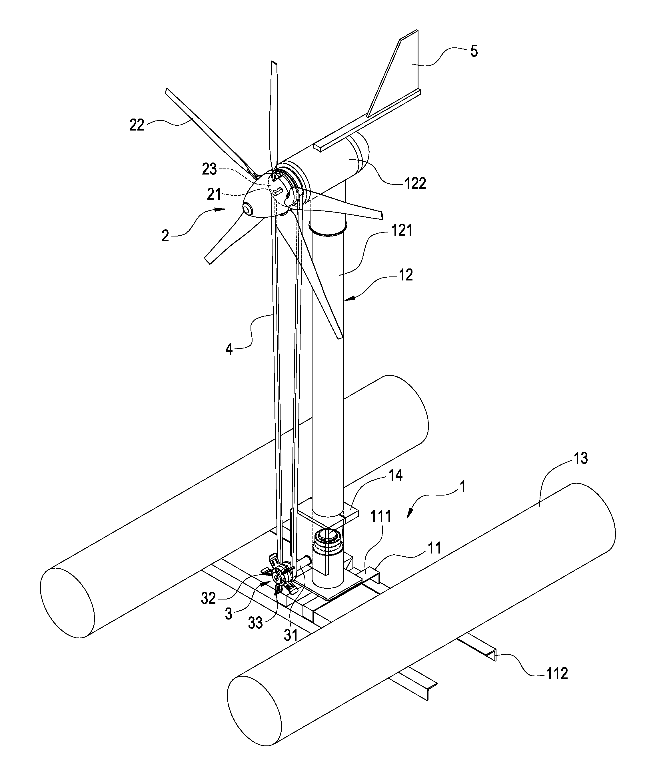
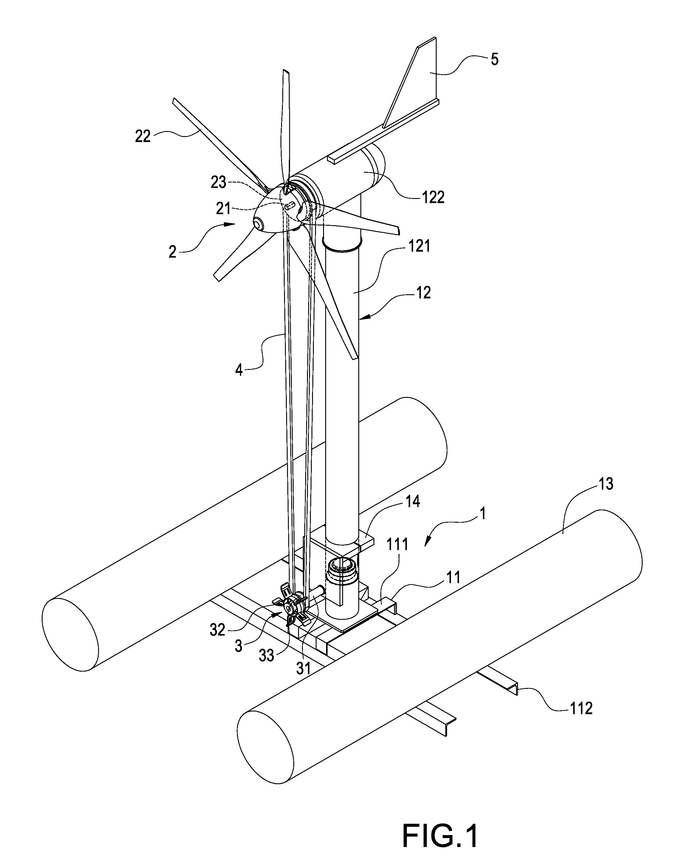
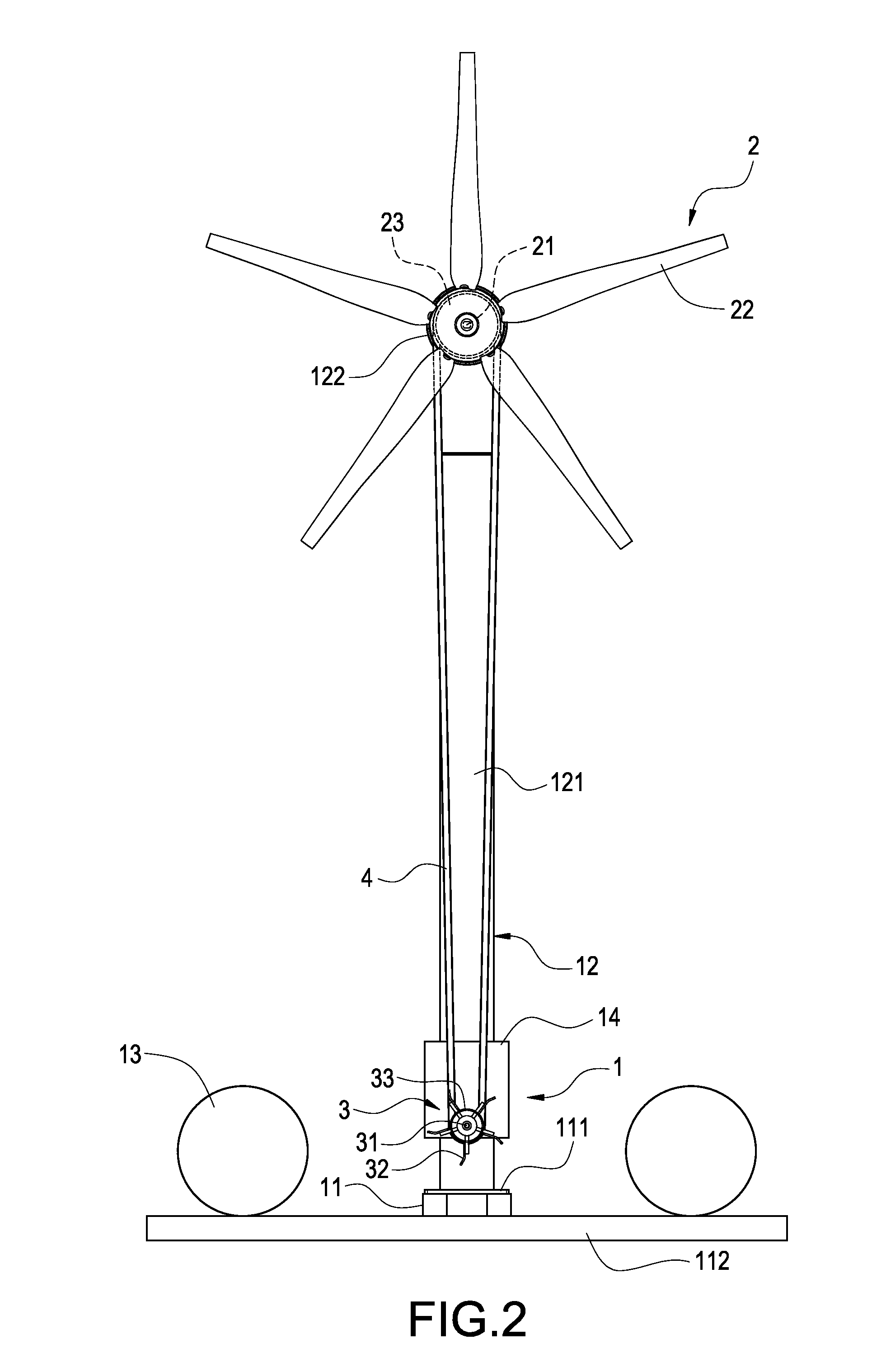
[0017]Please refer to FIG. 1. The present invention provides an energy-saving and wind-powered aerator, which includes a floating carrier 1, a wind turbine, a water stirrer 3, and a transmission element 4.

[0018]The floating carrier 1 has a bearing base 11. The bearing base 11 comprises a mounting block 111 and a connecting rod 112 connecting to the bottom surface of the bearing mounting block 111. The surface of the mounting block 111 is connected to an upright supporting structure 12. The surfaces on both ends of the connecting rod 112 are provided with a pair of cylindrical buoys 13. The supporting structure 12 comprises a longitudinal post 121 connected to ...


PUM

PropertyMeasurementUnit
densityaaaaaaaaaa
rotationaaaaaaaaaa
rotating energyaaaaaaaaaa

Abstract

An energy-saving and wind-powered aerator includes a floating carrier (1), a wind turbine (2), a water stirrer (3), and a transmission element (4). The floating carrier (1) has a supporting structure (12). The wind turbine (2) is connected to an upper portion of the supporting structure (12). The water stirrer (3) is mounted to the floating carrier (1). The transmission element (4) is connected to the wind turbine (2) and the water stirrer (3). The water stirrer (3) is rotated by means of the rotation of the wind turbine (2) and a driving action of the transmission element (4). With this arrangement, the wind turbine (2) is blown by natural and inexhaustible wind to rotate, so that the water stirrer (3) can be driven by the transmission element (4) to beat water rapidly, thereby increasing the amount of oxygen dissolved in the water and facilitating the decomposition of organic compounds in the water. In this way, the water quality can be improved and the amount of electricity consumed in aquaculture industries can be reduced to increase the profit.

Description

BACKGROUND OF THE INVENTION[0001]1. Field of the Invention The present invention relates to an aerator, and in particular to an energy-saving and wind-powered aerator capable of utilizing wind power as a driving power.[0002]2. Description of Prior Art[0003]As for aquaculture industries, eutrophication, acidification, and large amount of oxygen consumption in water have an important effect on their profit. If the water quality is to be improved, the amount of oxygen dissolved in the water is one of the most important conditions. However, when the external air is merely brought into direct contact with the water surface, the amount of oxygen dissolved in the water is insufficient. Although aquatic plants carry out photosynthesis in daytimes to increase the amount of oxygen dissolved in the water, the aquatic plants carry out respiration to consume oxygen, so that the amount of oxygen dissolved in the water is reduced. If the amount of oxygen dissolved in the water is lower than a limi...

Claims


Application Information

Patent Timeline
Patent Type & Authority Applications(United States)
IPC IPC(8): B01F3/04
CPCF03D1/001F03D11/04Y02E10/727F05B2240/93F05B2240/95F05B2230/6102F03D13/10F03D13/25Y02E10/72Y02P70/50
Inventor CHEN, SHIH-HSIUNG
Owner JETPRO TECH
Why Eureka
Try Eureka