
Method and system of managing virtualized physical memory in a multi-processor system

Active Publication Date: 2004-04-15
IBM CORP
View PDF19 Cites 15 Cited by
  • Summary
  • Abstract
  • Description
  • Claims
  • Application Information

AI Technical Summary

Problems solved by technology

This limits the operating system and applications to an address space determined by the actual physical memory installed in the system.
It would be expensive to dedicate a full complement of memory to each task and the operating system, especially since many processes use only a small part of their address spaces at any given time.
This interrupt and the kernel processing to allocate physical memory requires a significant amount of processing time and upsets the normal pipelining of instructions through the CPU.
The burden on the operating system of managing physical memory increases when the physical memory is reconfigured while the computer system is in operation.
If a memory device has been removed, the OS must invalidate the physical address space of the removed device and maintain the invalidated address space so that it can not be used, essentially leaving an unavailable block of space within the addressable space of the memory system.
These problems increase the overhead of the OS and complicate the control of memory.

Method used


Image

  • Method and system of managing virtualized physical memory in a multi-processor system
  • Method and system of managing virtualized physical memory in a multi-processor system
  • Method and system of managing virtualized physical memory in a multi-processor system

Examples


Embodiment Construction

)

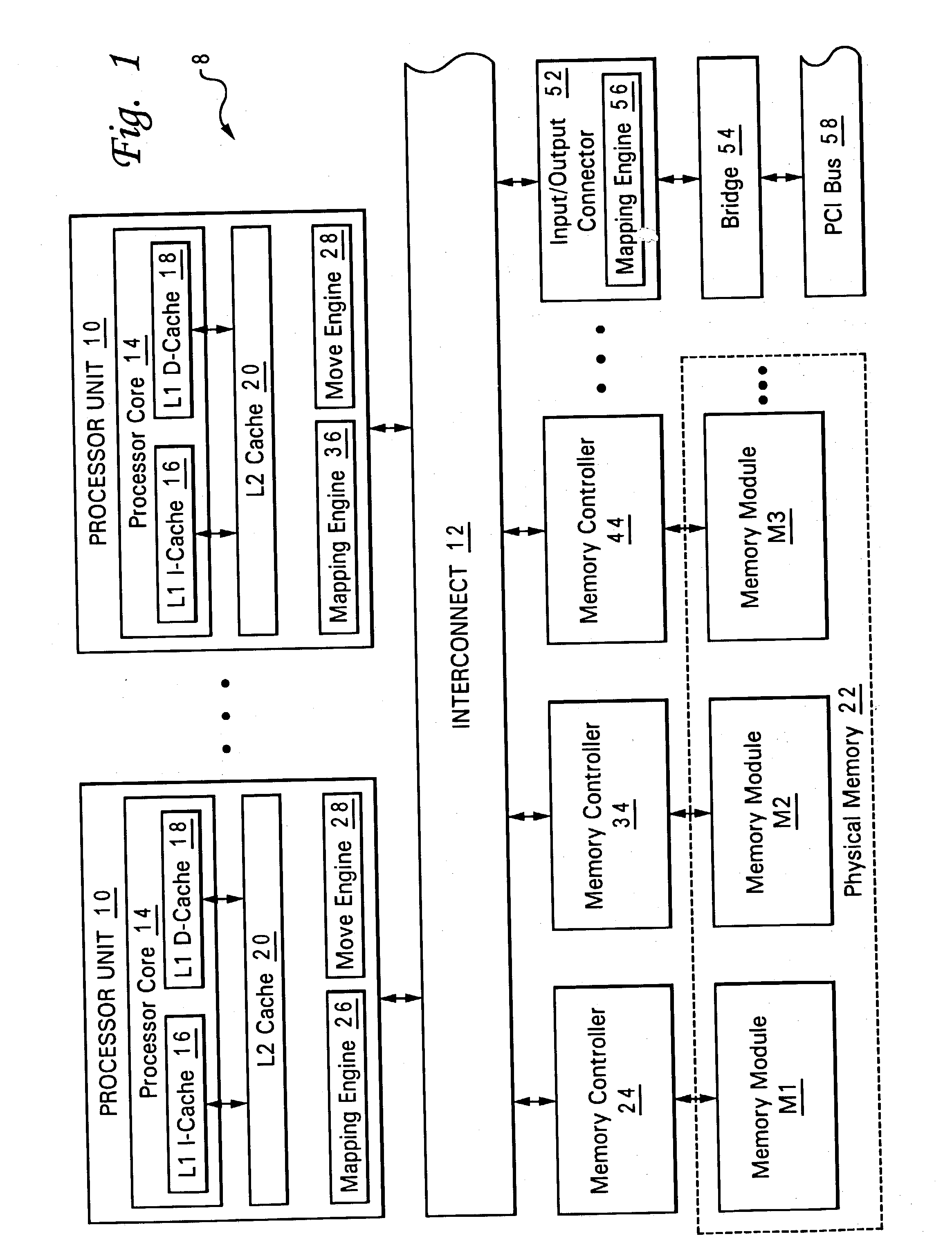
[0019] With reference now to the figures and in particular with reference to FIG. 1, there is illustrated a high-level block diagram of a multiprocessor (MP) data processing system that supports memory management of virtualized physical memory, in accordance with one embodiment of the present invention. As depicted, data processing system 8 includes a number (e.g., 64) of processing units 10 coupled for communication by a system interconnect 12. Each processing unit 10 is an integrated circuit including one or more processor cores 14. In addition to the registers, instruction flow logic and execution units utilized to execute program instructions, each of processor cores 14 includes associated level one (L1) instruction and data caches 16 and 18, which temporarily buffer instructions and operand data, respectively, that are likely to be accessed by the associated processor core 14.

[0020] As further illustrated in FIG. 1, the memory hierarchy of data processing system 8 also include...


PUM


Abstract

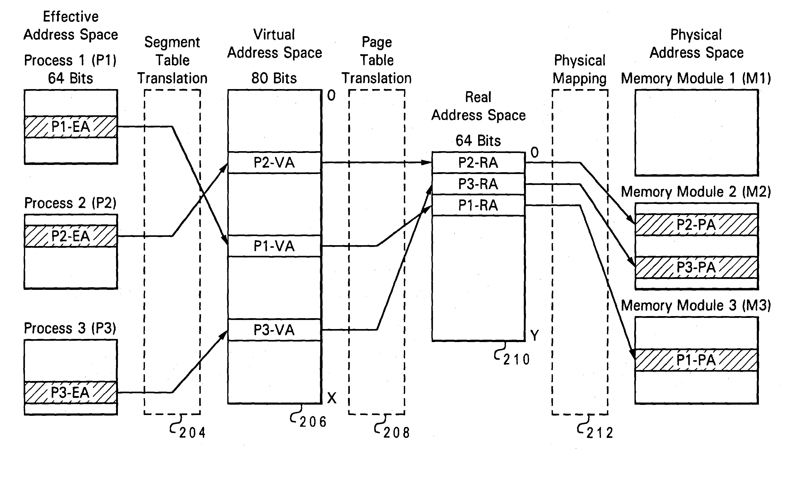
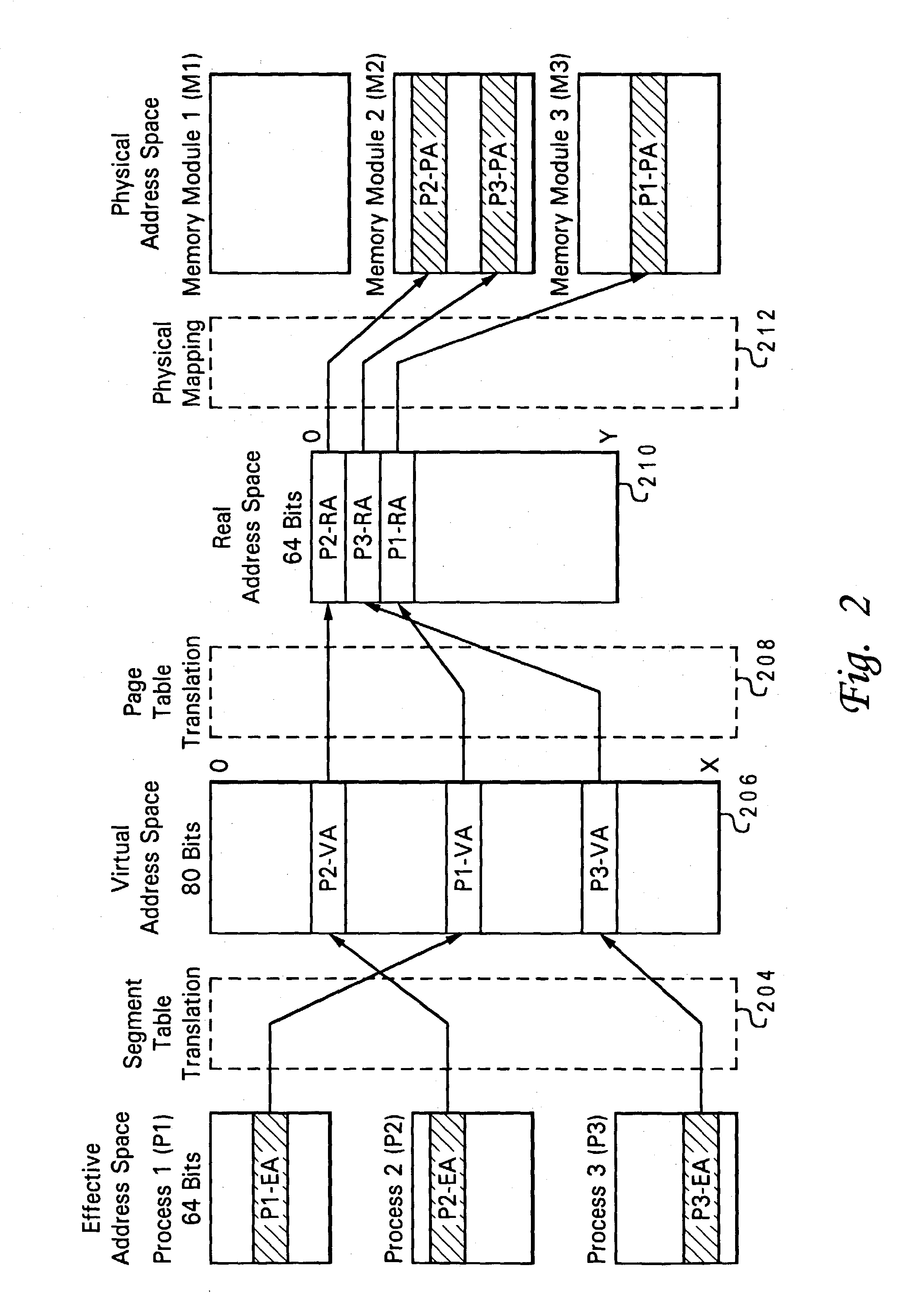
A processor contains a move engine and mapping engine that transparently reconfigure physical memory to accomplish addition, subtraction, or replacement of a memory module. A mapping engine register stores FROM and TO real addresses that enable the engines to virtualize the physical address of the memory module being reconfigured and provide the reconfiguration in real-time through the use of hardware functionality and not software. Using the FROM and TO real addresses to select a source and a target, the move engine copies the contents of the memory module to be removed or reconfigured into the remaining or inserted memory module. Then, the real address associated with the reconfigured memory module is re-assigned to the memory module receiving the copied contents, thereby creating a virtualized physical mapping from the addressable real address space being utilized by the operating system into a virtual physical address space. During the process of moving the memory contents, the mapping engine maps Write memory requests addressed to the real address space currently associated with the reconfigured memory module to both the FROM and TO real address space. As will be appreciated, a memory module can be inserted, removed or replaced in physical memory without the operating system having to direct and control the reconfiguration of physical memory to accomplish the physical memory change.

Description

[0001] The present invention is related to the subject matter of the following commonly assigned, copending U.S. patent application Ser. No. ______ (Docket No. AUS920020200US1) entitled "Method and System of Managing Virtualized Physical Memory in a Memory Controller and Processor System" and filed ______, 2002; Ser. No. ______ (Docket No. AUS920020202US1) entitled "Method and System of Managing Virtualized Physical Memory in a Data Processing System" and filed ______, 2002. The content of the above-referenced applications is incorporated herein by reference.[0002] 1. Technical Field[0003] The present invention relates in general to data processing and in particular to managing physical memory in a data processing system. Still more particularly, the present invention relates to a method and system for managing physical memory in a data processing system autonomously from operating system control.[0004] 2. Description of the Related Art[0005] In computer systems it is customary that...

Claims


Application Information

Patent Timeline
IPC IPC(8): G06F12/00G06F12/02G06F12/06G06F12/08
CPCG06F12/0646G06F12/0292G06F12/06
Inventor ARIMILLI, RAVI KUMARDODSON, JOHN STEVENGHAI, SANJEEVWRIGHT, KENNETH LEE
Owner IBM CORP
Learn More