Fire protection cover apparatus for structures

Inactive Publication Date: 2004-04-22
ROGERS WILLIAM +1
View PDF5 Cites 20 Cited by
  • Summary
  • Abstract
  • Description
  • Claims
  • Application Information

AI Technical Summary

Problems solved by technology

Hundreds of homes and outbuildings in several states have been lost this year alone.
While firefighters try to do their best to protect homes and other structures, the time spent doing so only serves to detract their attention and give the wildfire more time to grow.
This adds a great deal of risk to their efforts and to the operation itself.
If several homes catch fire, the intensity of the fire is magnified, threatening even more homes and wildland.
Because so many firefighters, fire trucks, and airborne resources are focused on a single fire, other areas may be left shorthanded.
All too often during periods of high fire danger, other fires are likely to start.
These other fires may bum unrestrained because firefighters committed to a wildland fire threatening homes will not be released to fight a fire that is burning in unpopulated wildlands.
The economic cost of wildland fires is staggering and a serious national problem.
Given the hazardous conditions created by wildfires, the owner of a home or other structure at this time has little recourse for home and out-building protection.
But these will still catch fire in the face of high heat or burning embers.
For the homeowner, keeping an appropriate amount of chemical sprays

Method used


Image

  • Fire protection cover apparatus for structures
  • Fire protection cover apparatus for structures
  • Fire protection cover apparatus for structures

Examples


Embodiment Construction

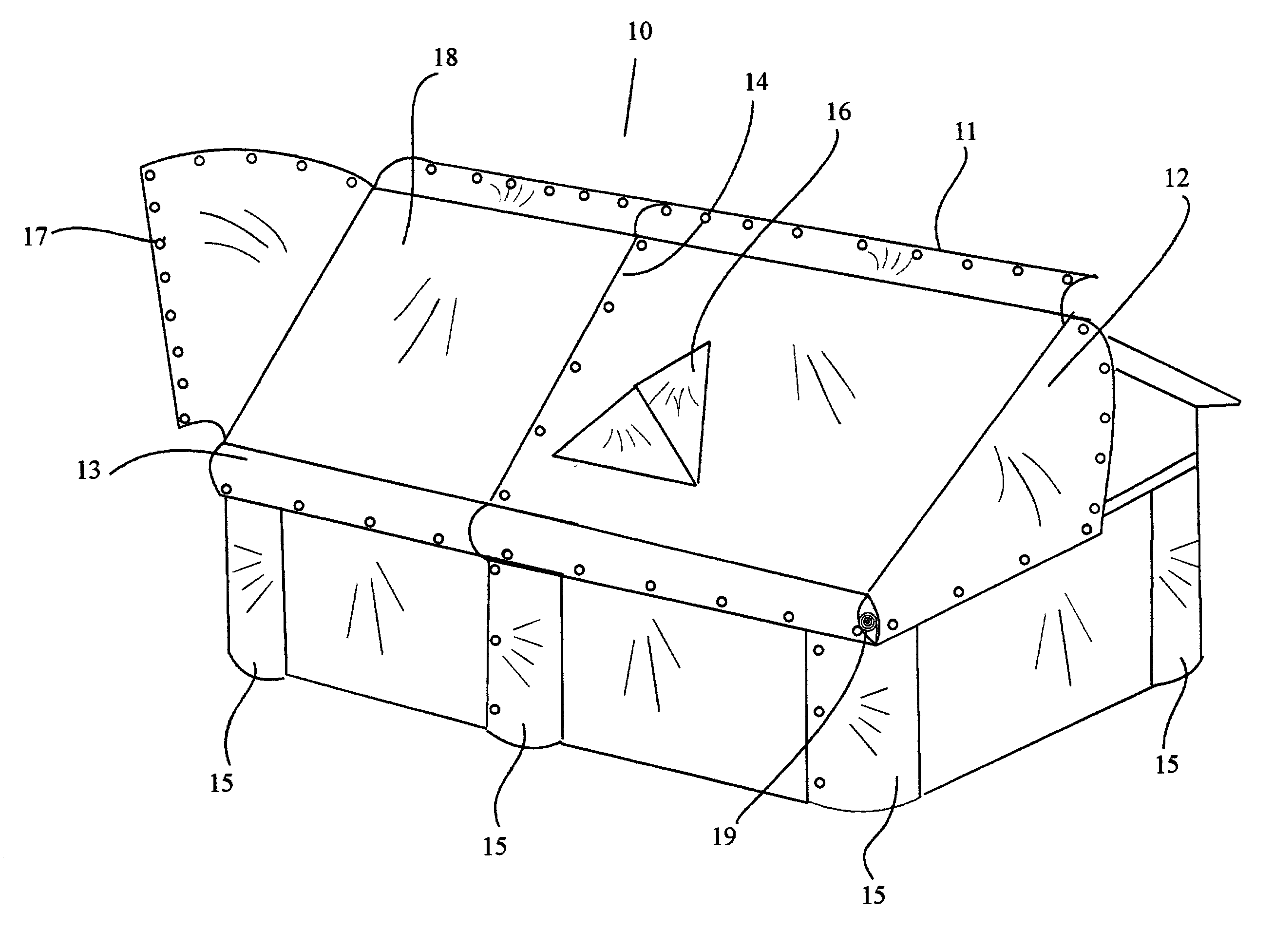
[0034] A fireproof cover apparatus for protecting structures in the path of a wildland fire, which embodies the concepts, and principles of the preferred embodiment of the invention is shown in the following illustrations.

[0035] Referring now to the drawings wherein the showings are for the purpose of illustrating the preferred embodiment of the invention only, and not for the purpose of limiting the same.

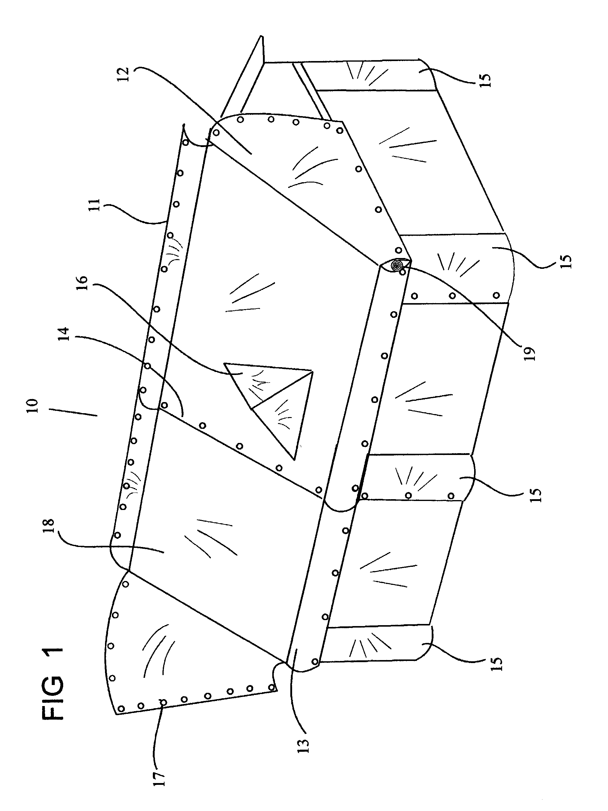
[0036] FIG. 1 shows the fireproof cover apparatus 10, installed in series on a structure and partially deployed and secured. The connector means 17, is utilized to secure the ridge flap 11, gable end flap 12, eaves flap 13, roof overlap flap 14, and elevation flap 15, to adjoining connection points on adjacent apparatus of the present invention. Connecting all flaps creates the fully sealed fire protection cover. The materials to be used for the fireproof cover apparatus are only limited by their strength, heat resistance, weight, and costs. The preferred material of construction f...


PUM


Abstract

An apparatus, a wildfire protection method for houses and other structures from the destructive forces of a wildland fire. The current form of the preferred embodiment consists of a highly fireproof material, which is pre-fitted to cover each area of structure including gables or dormers one section at a time. The material is contained on a fireproof deployment apparatus such as a roller means having a retractable mechanism. The deployment apparatus is contained and secured within a housing, this housing being supported by firmly mounting it to strategic areas of the architectural structure. Once installed, deployment of the fireproof covering material is accomplished by unrolling the material from one side of the fireproof deployment apparatus. Each pre-fitted section of fireproof material contains reinforced edges, which are fitted with multiple fasteners by which to attach one section of said fireproof material to another as each is deployed from a series of apparatus. Each section of material is deployed in sequence and fastened to other nearby sections. The fireproof material once deployed by sections and fastened over the entire structure will provide protection from the high heat and burning embers associated with wildfires. Total structure coverage is accomplished very quickly by using several of these apparatus in series, each of which are strategically attached to the structure architecture.

Description

[0001] 1. Field of Invention[0002] There is the severe lack of quickly and easily deployable exterior fire protection for homes and other structures in the path of a wildfire. A very great need is apparent for a re-usable, affordable covering means that will not loose its fire protection properties even when deployed for many days in any type of weather.[0003] 2. Description of the Related Art[0004] There are two possible sources that will cause a home to ignite during a wildland fire: either from direct flames and / or from firebrands accumulating directly on the home. Even the large flames of high intensity do not directly ignite homes at distances beyond 200 feet. Fires adjacent to a home do not ignite it and firebrands can only ignite a home through contact.[0005] The prevalence of wildfires around the country remains a significant public concern. Hundreds of homes and outbuildings in several states have been lost this year alone. While firefighters try to do their best to protect...

Claims


Application Information

Patent Timeline
IPC IPC(8): A62C2/10A62C3/02E04B1/94E04H9/14E04H15/02E04H15/54
CPCA62C2/10A62C3/0214A62C3/0257Y10S52/12E04H9/14E04H15/02E04H15/54E04B1/94
Inventor ROGERS, WILLIAMHOLLIDAY, CHRISTIE
Owner ROGERS WILLIAM
Why Eureka
Try Eureka