Combined cabin heater and egr heat exchanger

a heat exchanger and cabin heater technology, applied in indirect heat exchangers, machines/engines, light and heating apparatus, etc., can solve the problems of increasing the cost of additional heat exchangers, pipework and valves, and high production costs, so as to maintain customer performance, high fuel economy, and affordable cost

Inactive Publication Date: 2012-07-19
FORD GLOBAL TECH LLC
View PDF3 Cites 27 Cited by
  • Summary
  • Abstract
  • Description
  • Claims
  • Application Information

AI Technical Summary

Benefits of technology

[0003]There is an increasing demand in the automobile industry to provide fuel economy and emissions at an affordable cost whilst maintaining customer performance. This is felt very strongly with cabin heater performance where, due to the demand for very high fuel economy from the engine, there is no waste heat left for transfer to the engine coolant for use in a cabin heater. As a consequence auxiliary heaters are being fitted to vehicles. Currently the main type of auxiliary heater is a supplementary electric heater which, while effective in providing customer comfort, does so at a reasonably high cost and poor fuel economy.

Problems solved by technology

Currently the main type of auxiliary heater is a supplementary electric heater which, while effective in providing customer comfort, does so at a reasonably high cost and poor fuel economy.
One disadvantage of such a low pressure system is the increased cost associated with the additional heat exchangers, pipework and valves.
There are a number of disadvantages with such a system, firstly the arrangement of the exhaust gas heat exchanger 111 and bypass passage 113 are expensive to produce and are difficult to package in the confined space of a modern motor vehicle.
Such ingestion is disadvantageous as it can result in damage to the compressor 80 or to the engine 105.
Also the impingement of water droplets in the form of the entrained condensate against the blades of the compressor is likely to reduce its service life even if instantaneous damage does not occur.

Method used


Image

  • Combined cabin heater and egr heat exchanger
  • Combined cabin heater and egr heat exchanger
  • Combined cabin heater and egr heat exchanger

Examples


Embodiment Construction

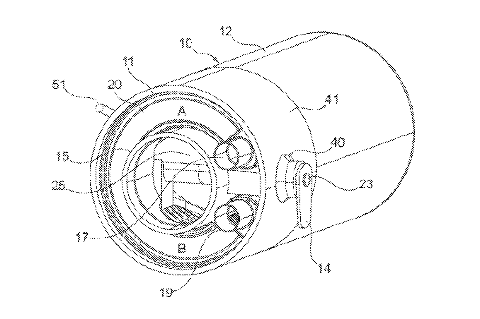
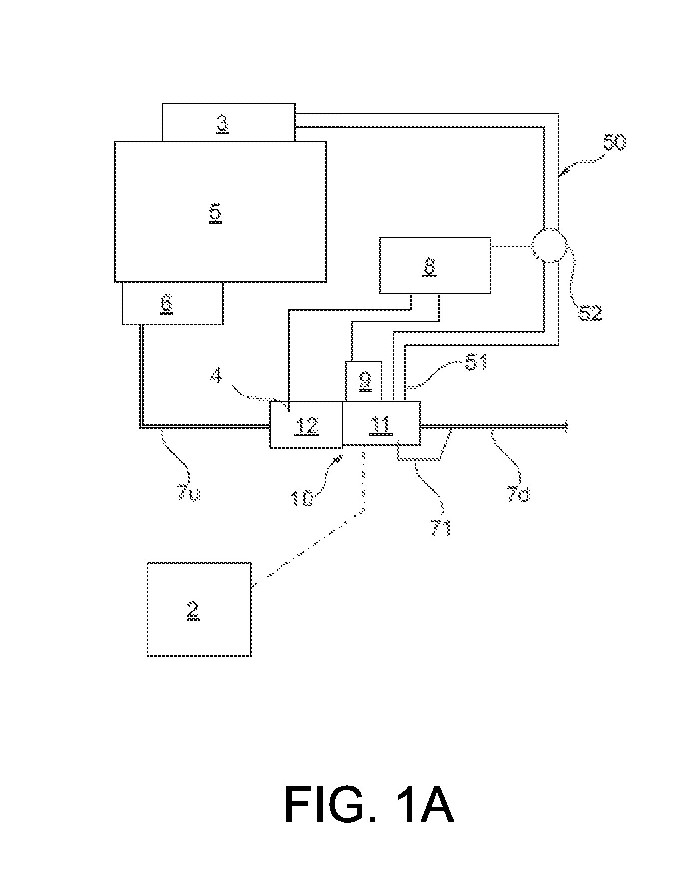
[0023]With particular reference to FIG. 1A there is shown an internal combustion engine 5 having an exhaust manifold 6 to which is connected an exhaust pipe 7u leading to an exhaust gas inlet 13 (not shown in FIG. 1A) to a combined emission control device and low pressure exhaust gas recirculation heat exchanger assembly 10.

[0024]The combined emission control device and cooler assembly 10 comprises an emission control device, such as a catalytic converter, 12 and a heat exchanger in the form of an exhaust gas heat exchanger 11 positioned downstream from the emission control device 12. The emission control device 12 is connected to the exhaust gas inlet 13 so that it may receive exhaust gas from engine 5. The exhaust gas heat exchanger 11 extracts heat from the exhaust gas passing through it which may be used to heat a cabin of a motor vehicle by a cabin heater 2 in the form of a coolant to air heat exchanger.

[0025]A second exhaust pipe 7d transfers exhaust gas from an outlet of tube...


PUM


Abstract

A combined emission control device and exhaust gas heat exchanger for connection to the exhaust gas flow from an engine of a motor vehicle is disclosed having a number of exhaust gas transfer passages and a number of coolant passages so as to permit heat to be transferred from exhaust gas flowing through the exhaust gas heat exchanger to coolant used to supply heating for a cabin of the motor vehicle. The exhaust gas heat exchanger includes a tapping to permit cooled exhaust gas to be extracted for use in a Low Pressure Exhaust Gas Recirculation system. The exhaust gas heat exchanger thereby provides dual functionality being able to recuperate heat for use in a cabin heater and cool exhaust gas for use in the Low Pressure Exhaust Gas Recirculation system.

Description

RELATED APPLICATIONS[0001]The present application claims priority to United Kingdom Patent Application No. 1100724.2, filed on Jan. 17, 2011, the entire contents of which are hereby incorporated by reference for all purposes.FIELD[0002]This disclosure relates to heat exchangers and in particular to an exhaust gas heat exchanger for an internal combustion engine.BACKGROUND AND SUMMARY[0003]There is an increasing demand in the automobile industry to provide fuel economy and emissions at an affordable cost whilst maintaining customer performance. This is felt very strongly with cabin heater performance where, due to the demand for very high fuel economy from the engine, there is no waste heat left for transfer to the engine coolant for use in a cabin heater. As a consequence auxiliary heaters are being fitted to vehicles. Currently the main type of auxiliary heater is a supplementary electric heater which, while effective in providing customer comfort, does so at a reasonably high cost...

Claims


Application Information

Patent Timeline
Patent Type & Authority Applications(United States)
IPC IPC(8): F02M25/07F01N3/02
CPCB60H1/025F28D9/0093F02M25/0709F02M25/0718F02M25/0728F02M25/0735F02M25/0737F02M25/074Y02T10/121F02M25/0729F02M25/0717F02M25/0734F28D9/0012F28D9/0031F01N2240/02F02M26/14F02M26/06F02M26/15F02M26/25F02M26/26F02M26/29F02M26/30F02M26/32F02M26/35B60H1/18F01N3/005
Inventor CAINE, JONATHAN EDWARD
Owner FORD GLOBAL TECH LLC
Why Eureka
Try Eureka