Electrode member for retinal stimulation, and artificial retinal device using the electrode member
- Summary
- Abstract
- Description
- Claims
- Application Information
AI Technical Summary
Problems solved by technology
Method used
Image
Examples
first embodiment
[0059] First Embodiment
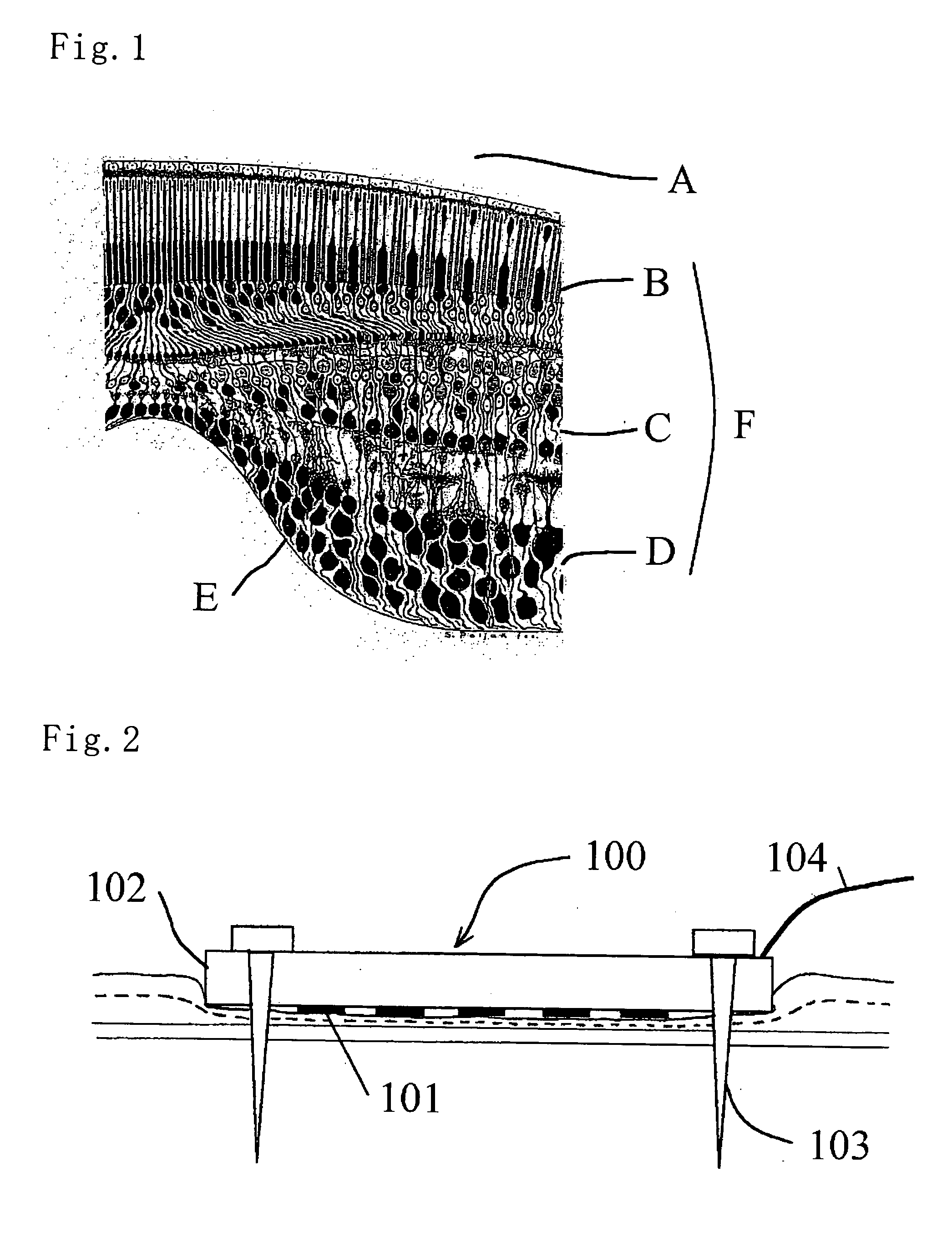
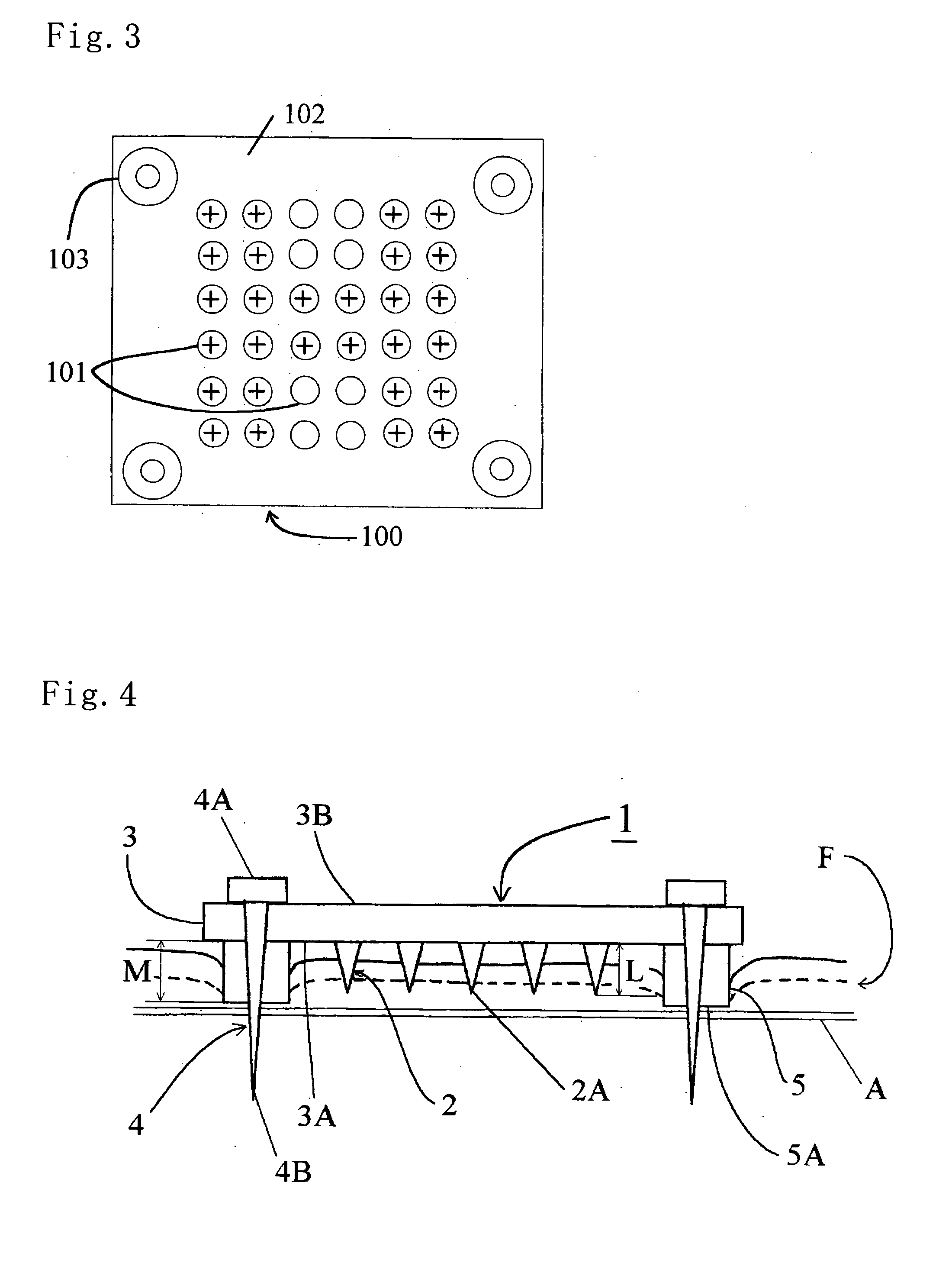
[0060] A first embodiment will be described with reference to FIGS. 1 to 8. FIG. 1 is a side sectional view of a retina F of a healthy person. The sclera A is located outside the retina F and covers an outer face of the eyeball. Inside the sclera A are photoreceptors B, retinal bipolar cells C and retinal ganglion cells D sequentially in this order. The electrode member 1 for retinal stimulation of the embodiment (hereinafter referred to as "electrode member 1") is expected to be applied to patients of Retinitis Pigmentosa and age-related macular degeneration (ARMD). In symptoms of these patients, photoreceptors B are degenerated such that light cannot be converted to electric signals. Next, a visual path such as the retinal bipolar cells C and retinal ganglion cells D fails to function, which failure results in loss of sight. However, it is known that about 70% of the retinal bipolar cells C and about 30% of the retinal ganglion cells D are left in a patient ...
second embodiment
[0073] Second Embodiment
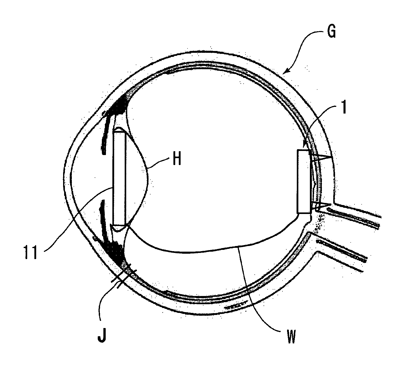
[0074] A second embodiment will be described with reference to FIGS. 9 to 11. Firstly, the arrangement of the second embodiment will be described with reference to FIG. 11. The artificial retina device 10 comprises the electrode member 1 and the signal transmitting section 11. Both members 1 and 11 are connected to each other by the electric wire W. The artificial retina device 10 is designed to be attached to an inner part of the eyeball G. The signal transmitting section 11 is a receiver which receives image-forming electric signals from a transmitter 12 provided outside the eyeball G, by a radio system. The signal transmitting section 11 has an outer diameter which ranges from about 5 mm to about 8 mm and is substantially as large as or slightly larger than an inner diameter of a crystal lens H. A signal control device 13 (including for example, a CCD camera, microcomputer, etc.) is connected to the transmitter 12 for generating and controlling image signa...
third embodiment
[0077] Third Embodiment
[0078] A third embodiment will be described with reference to FIGS. 12 to 16. Firstly, the arrangement of the second embodiment will be described with reference to FIG. 14. The artificial retina device 20 comprises the electrode member 1, the signal transmitting section 21 transmitting electric signals to the electrode member 1, a control device 22 (including a microcomputer) controlling the electric signals and a fixing section 23. The signal transmitting section 21 is a receiver which receives image-forming electric signals from a transmitter 24 provided outside the eyeball G, by a radio system. The control device 22 includes a control circuit 25 and a power supply device 26. The power supply device 26 is a secondary cell such as a lithium cell. The fixing section 23 is provided for fixing the electrode member 1 to the retina (the construction thereof will be described in detail later). The fixing section 23 also serves as a coil to supply to the power suppl...
PUM
 Abstract
Description
Claims
Application Information
 - R&D
- Intellectual Property
- Life Sciences
- Materials
- Tech Scout
- Unparalleled Data Quality
- Higher Quality Content
- 60% Fewer Hallucinations
Browse by: Latest US Patents, China's latest patents, Technical Efficacy Thesaurus, Application Domain, Technology Topic, Popular Technical Reports.
© 2025 PatSnap. All rights reserved.Legal|Privacy policy|Modern Slavery Act Transparency Statement|Sitemap|About US| Contact US: help@patsnap.com


