Image recognition method and apparatus utilizing edge detection based on magnitudes of color vectors expressing color attributes of respective pixels of color image

a color image and image recognition technology, applied in image analysis, image enhancement, instruments, etc., can solve the problems of inability to apply prior art methods of improving accuracy, difficult to apply image recognition to satellite images or aerial photographs, complex image contents,

Inactive Publication Date: 2004-04-29
PANASONIC CORP
View PDF6 Cites 33 Cited by
  • Summary
  • Abstract
  • Description
  • Claims
  • Application Information

AI Technical Summary

Benefits of technology

[0024] In that way, since all of the color information contained in the image can be utilized to perform edge detection, the detection can be more accurately and reliably performed than has been possible in the prior art.
[0218] The result obtained is as shown in the lower part of FIG. 46. As shown, the shapes of many vehicles have been eliminated, thereby enabling the buildings to be more easily recognized, without reducing the accuracy of extracting the shapes of the buildings.

Problems solved by technology

However in the case of recognizing shapes within satellite images or aerial photographs, such prior art methods of improving accuracy cannot be applied.
Furthermore, a single image may contain many categories of image data, such as image data corresponding to building, rivers, streets, etc., so that the image contents are complex.
As a result, the application of image recognition to satellite images or aerial photographs is extremely difficult.
However with the method described in Japanese patent HEI 6-83962, only the zero-crossing method is used, so that it is not possible to determine edge directions, since only each local maximum of variation of a gradient of a color attribute is detected, irrespective of the direction along which that variation is oriented.
However even if the results thus obtained are combined, accurate edge directions cannot be detected.
Specifically, the edge directions which result from using intensity values, hue values and saturation values may be entirely different from one another, so that accurate edge detection cannot be achieved by taking the average of these results.
However such a type of image recognition apparatus has not been available in the prior art.
However if processing is applied to RGB data which contain some degree of scattering of the color values, and a transform from RGB to HSI color space is executed, then the resultant values of saturation will be unstable (i.e., will tend to vary randomly with respect to the correct values) within those regions of the image in which the intensity values are high, and also within those regions of the image in which the intensity values are low.
For that reason it has been difficult in the prior art to utilize the color saturation information contained in a color image, in image recognition processing.
Furthermore if a substantial degree of smoothing processing is applied to an image which is to be subjected to image recognition, in order to suppress the occurrence of such noise, then this has the effect of blurring the image, causing rounding of the shapes of edges and also merging together any edges which are located closely mutually adjacent.
As a result, the accuracy of extracting edge information will be reduced.
Conversely, if only a moderate degree of smoothing processing is applied to the image that is to be subjected to image recognition, or if smoothing processing is not applied to the image, then the accuracy of extraction of shapes from the image will be high, but there will be a high level of noise in the results so that reliable extraction of the shapes of the required objects will be difficult to achieve.
Moreover in the prior art, there has been no simple and effective method of performing image recognition processing to extract the shapes of objects which are to be recognized, which will eliminate various small objects in the image that are not intended to be recognized (and therefore can be considered to constitute noise) without distorting the shapes of the objects which are to be recognized.
It is known that when image data are transformed from a form such as RGB color values into an HSI color space, instability (i.e., random large-scale variations) may occur in the saturation values which are obtained as a result of the transform.
This instability of saturation values is most prevalent in those regions of a color image where the intensity values are exceptionally low, and also in those regions where the intensity values are exceptionally high.
This is a characteristic feature of such a transform operation, and causes noise to appear in the results of edge detection that is applied to such HSI-transformed image data and utilizes the saturation information, due to the detection of spurious edge portions as a result of abrupt changes in saturation values between adjacent pixels.

Method used


Image

  • Image recognition method and apparatus utilizing edge detection based on magnitudes of color vectors expressing color attributes of respective pixels of color image
  • Image recognition method and apparatus utilizing edge detection based on magnitudes of color vectors expressing color attributes of respective pixels of color image
  • Image recognition method and apparatus utilizing edge detection based on magnitudes of color vectors expressing color attributes of respective pixels of color image

Examples


first embodiment

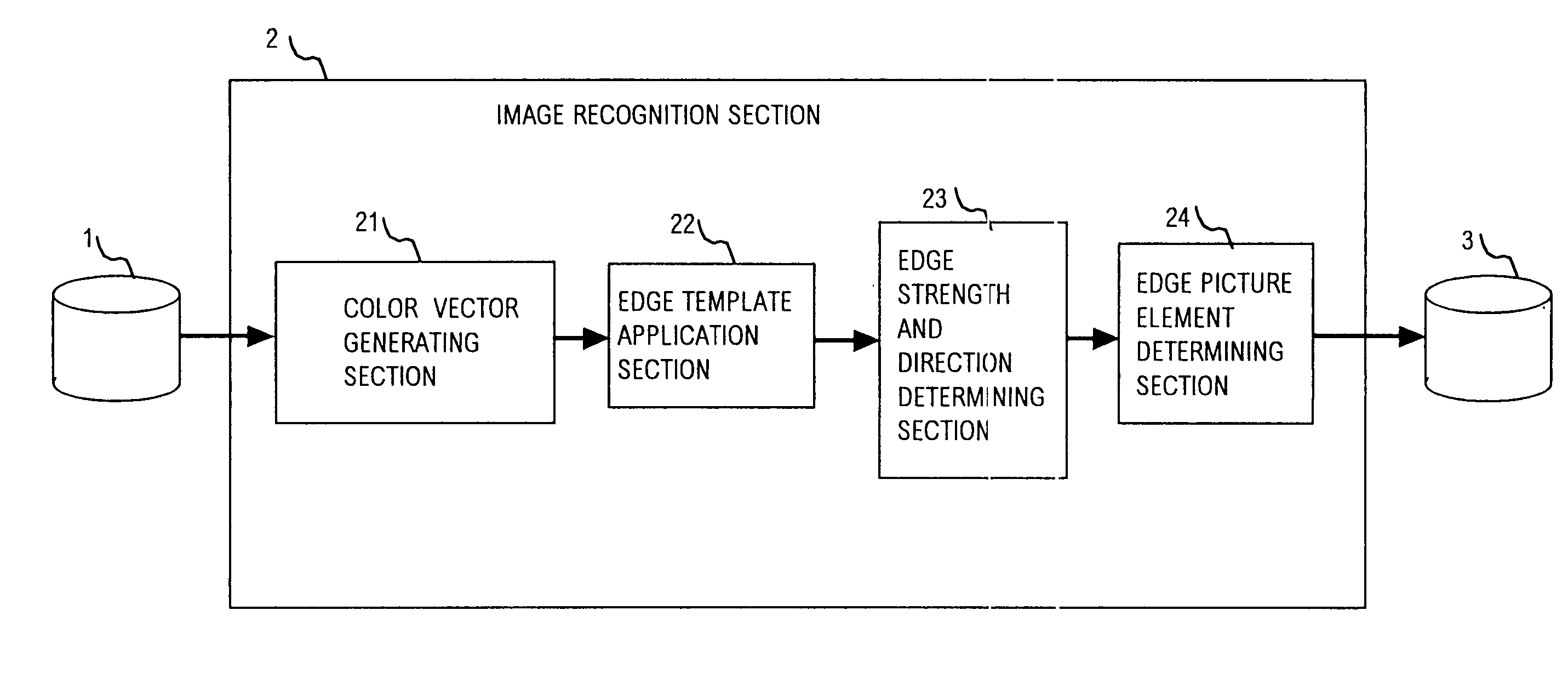
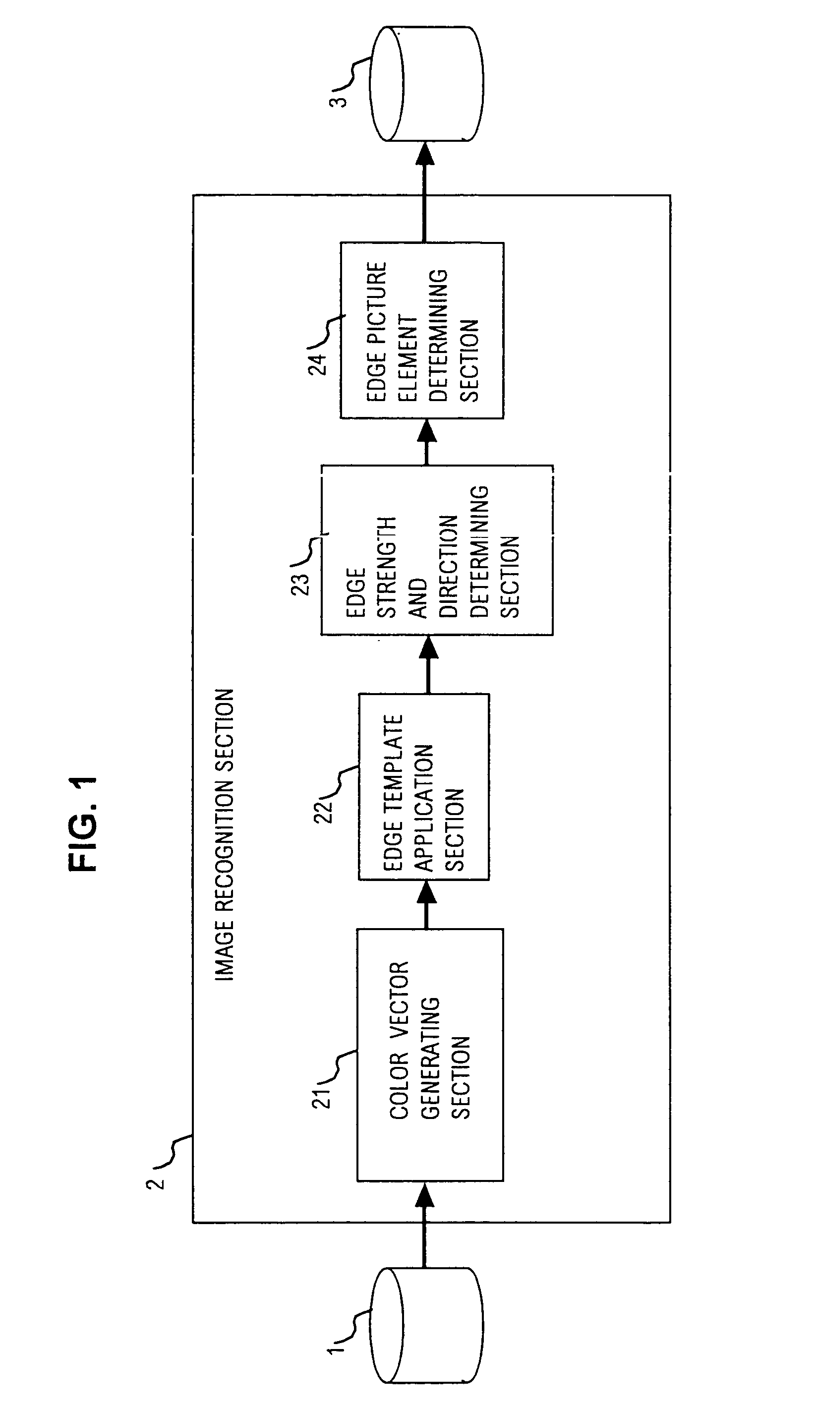
[0095] an image recognition apparatus according to the present invention will be described referring to FIG. 1. As used herein in referring to embodiments of the invention, the term "image recognition" is used in the limited sense of signifying "processing the data of an original color image to derive shape data, i.e., data of an edge image which expresses only the outlines of objects appearing in the original color image". The apparatus is formed of a color image data storage section 1 which stores the data of a color image that is to be subjected to image recognition processing, an image recognition processing section 2 which performs the image recognition processing of the color image data, and a shape data storage section 3 which stores shape data expressing an edge image, which have been derived by the image recognition processing section 2.

[0096] The image recognition processing section 2 is made up of a color vector data generating section 21, an edge template application sec...

second embodiment

[0128] FIG. 16 is a flow diagram showing the basic features of the operation of the

[0129] Steps 11, 12 and 13 of this flow diagram are identical to those of the basic flow diagram of the first embodiment shown in FIG. 5. Step 10 of this flow diagram differs from that of the first embodiment in that color vector modulus adjustment can be performed, as described hereinafter. A new step 20 is executed as follows.

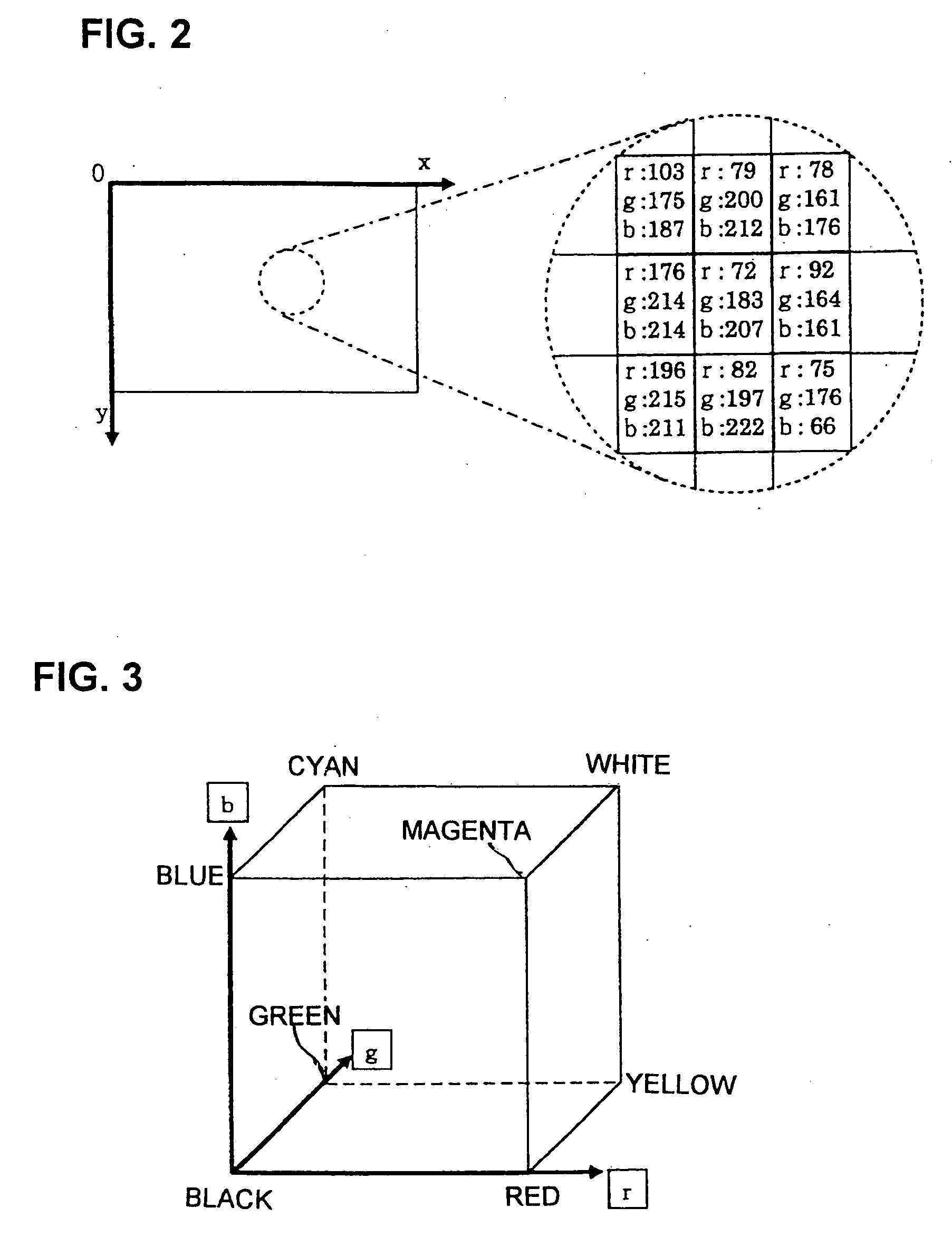
[0130] Step 20: the color attribute data of each pixel are transformed from the RGB color space to coordinates of the color space shown in FIG. 17. Specifically, each set of pixel values r(x, y), g(x, y), b(x, y) is operated on, using equation (7), to obtain a corresponding set of coordinates c1(x, y), c2(x, y), c3(x, y). Here, c1 expresses a form of intensity value for the pixel, i.e., as the average of the r, g and b values of the pixel, c2 expresses the proportion of the red component of that pixel in relation to the total of the red, green and blue values for that pel, and ...

third embodiment

[0150] Step 20: the pixel values are transformed from the RGB color space to the coordinates of the cylindrical HSI color space shown in FIG. 20, using equation (9) as described hereinabove for the Equation (11) is then applied to transform the respective sets of h, s, i values obtained for each of the pixels of the color image pixel to the coordinates of a color space of the inverted conical form shown in FIG. 24, i.e., to coordinates h', s', i' of a modified form of HSI color space. 10 h ' = ( x , y ) = h ( x , y ) s ' = ( x , y ) =i ( x , y ) max_values ( x , y ) i '( x , y ) = i ( x , y ) ( 11 )

[0151] Thus, the color space transform operation is performed by applying equation (11) above to convert each h(x, y), s(x, y), i(x, y) set of values, for the pixel located at position (x, y) of the color image, to a set of h'(x, y), s'(x, y), i'(x, y) values respectively. This transform does not produce any change between h(x, y) and h'(x, y), or between i(x, y) and i'(x, y), however as...


PUM


Abstract

An image recognition apparatus operates on data of a color image to obtain an edge image expressing the shapes of objects appearing in the color image, the apparatus including a section for expressing the color attributes of each pixel of the image as a color vector, in the form of a set of coordinates of an orthogonal color space, a section for applying predetermined arrays of numeric values as edge templates to derive for each pixel a number of edge vectors each corresponding to a specific edge direction, with each edge vector obtained as the difference between weighted vector sums of respective sets of color vectors of two sets of pixels which are disposed symmetrically opposing with respect to the corresponding edge direction, and a section for obtaining the maximum modulus of these edge vectors as a value of edge strength for the pixel which is being processed. By comparing the edge strength of a pixel with those of immediately adjacent pixels and with a predetermined threshold value, a decision can be reliably made for each pixel as to whether it is actually located on an edge and, if so, the direction of that edge.

Description

[0001] 1. Field of Application[0002] The present invention relates to an image recognition method and an image recognition apparatus for use in an image recognition system, for extracting from a color image the shapes of objects which are to be recognized. In particular, the invention relates to an image recognition apparatus which provides a substantial improvement in edge detection performance when applied to images such as aerial photographs or satellite images which exhibit a relatively low degree of variation in intensity values.[0003] 2. Description of Prior Art[0004] In the prior art, various types of image recognition apparatus are known, which are intended for various different fields of application. Typically, the image recognition apparatus may be required to extract from an image, such as a photograph, all objects having a shape which falls within some predetermined category.[0005] One approach to the problem of increasing the accuracy of image recognition of the content...

Claims


Application Information

Patent Timeline
Patent Type & Authority Applications(United States)
IPC IPC(8): G06T5/00G06V20/13G06T7/60
CPCG06K9/0063G06T7/0083G06T2207/30184G06T2207/10024G06T2207/10032G06T7/408G06T7/12G06T7/90G06V20/13
Inventor TAKAHASHI, EIJI
Owner PANASONIC CORP
Why Eureka
Try Eureka