Ceiling air passage system for vehicle air conditioner
- Summary
- Abstract
- Description
- Claims
- Application Information
AI Technical Summary
Benefits of technology
Problems solved by technology
Method used
Image
Examples
first embodiment
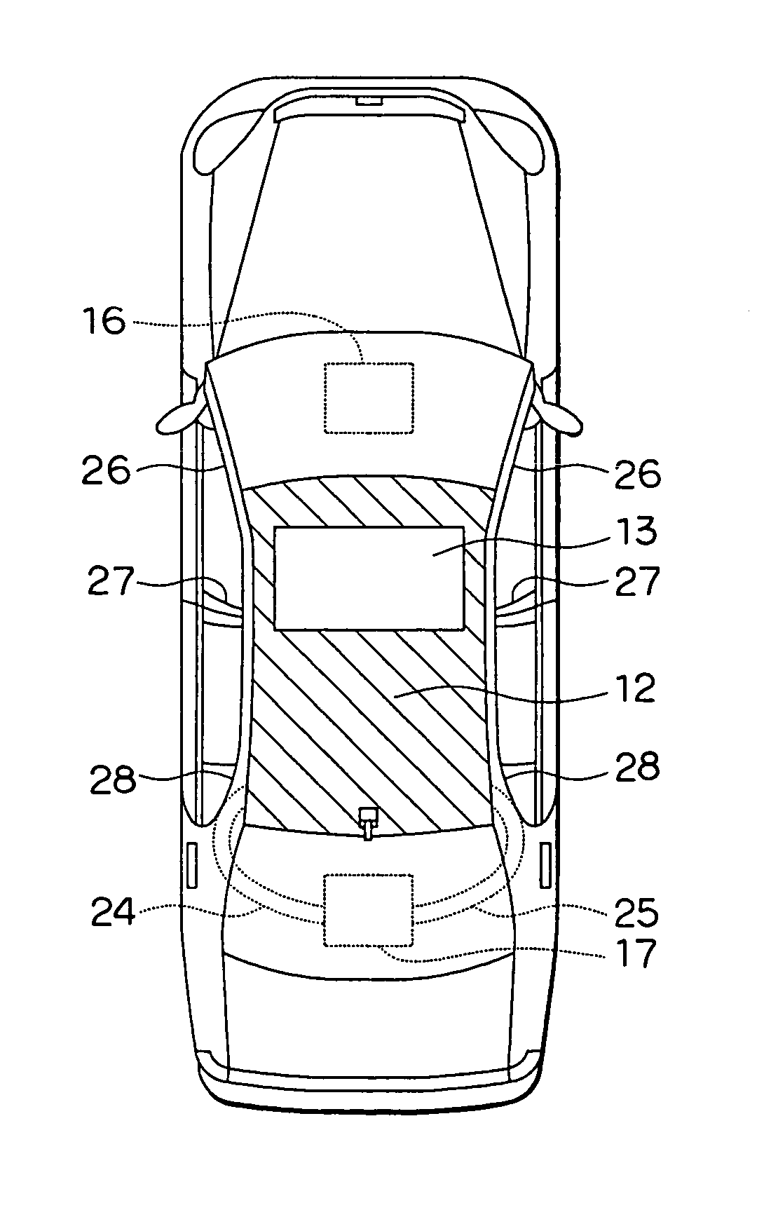
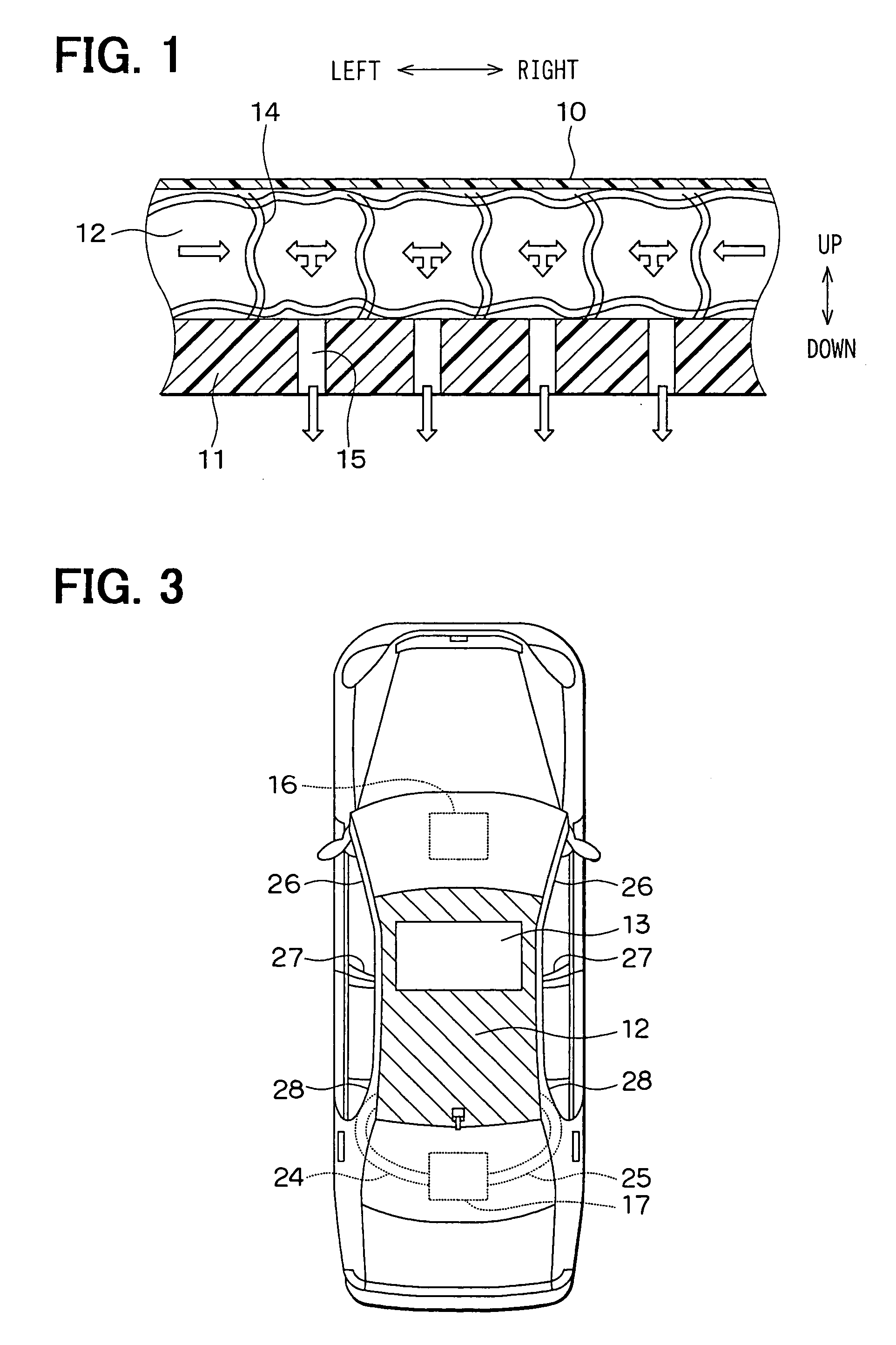
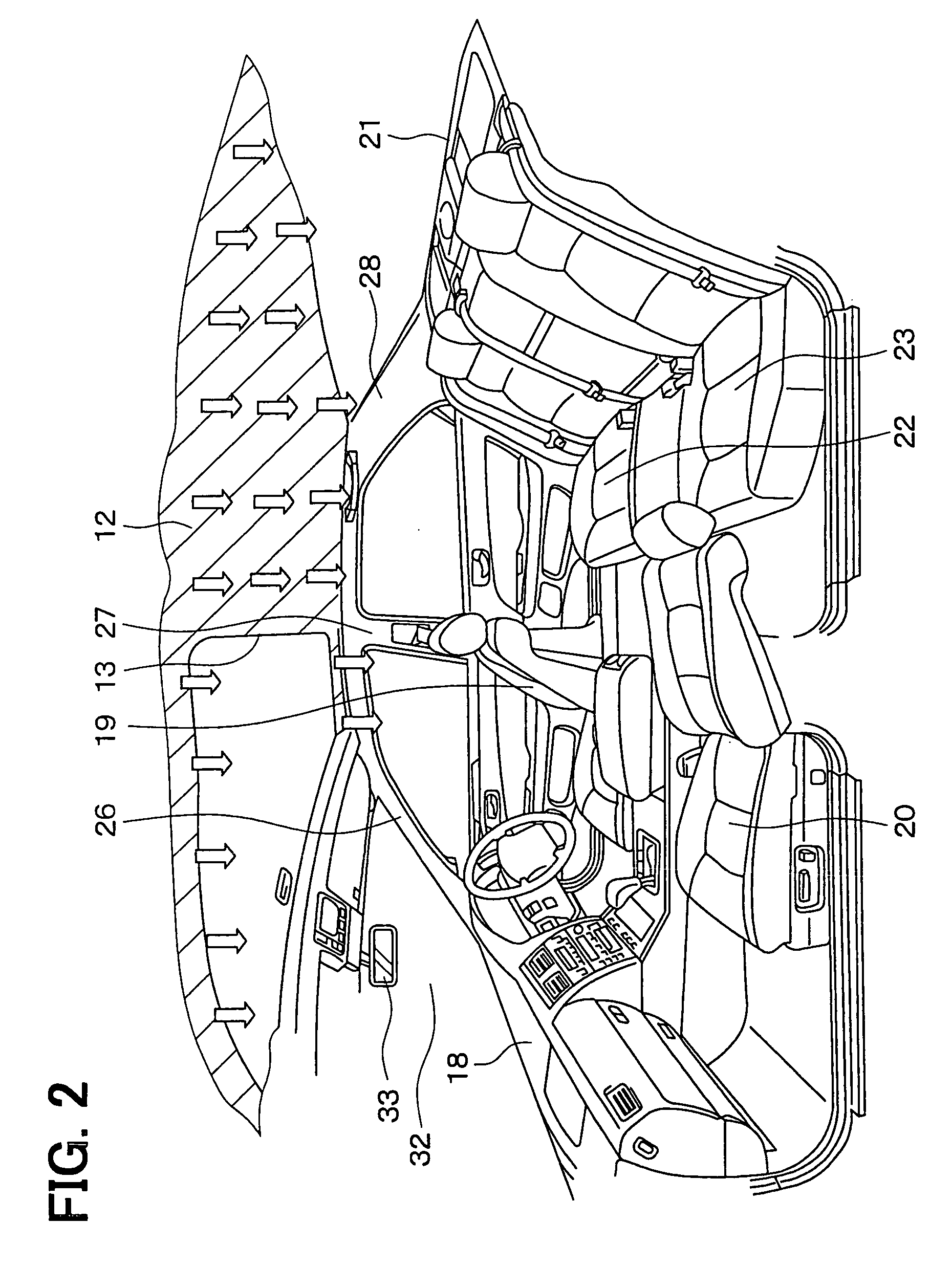
[0027] The first embodiment of the present invention will be now described with reference to FIGS. 1-4. As shown in FIG. 1, a ceiling portion of a vehicle includes a heat insulating member 10 disposed at a lower side (back side) of a vehicle roof (not shown). The heat insulating member 10 is a sheet made of a resin material having high heat-insulating performance and high sealing performance. A ceiling base member 11 is disposed at a lower side of the heat insulating member 10 to have a predetermined distance therebetween. The ceiling base member 11 is made of a resin, and has a thickness much thicker than a thickness of the heat insulating member 10. A base plate of the ceiling portion in a passenger compartment shown in FIG. 2 is constructed with the ceiling base member 11. The predetermined distance is provided between the heat insulating member 10 at the upper side and the ceiling base member 11 at the lower side, thereby providing an air passage 12 between the heat insulating m...
second embodiment
[0036] In the above-described first embodiment, the air passage (slant line area in FIG. 3) 12 is provided so as to enclose the entire periphery of the rectangular sunroof opening 13. However, in the second embodiment, as shown in FIG. 5, the air passage 12 is provided in a U-shape so as to enclose the three edges of the rectangular sunroof opening 13. Specifically, since the sunroof opening 13 is located at a front side of the ceiling portion in the vehicle front-rear direction, the air passage 12 is provided in the U-shape so as to enclose the rectangular sunroof opening 13 at two edges in the vehicle right-left direction and at one edge on the vehicle rear side. In the second embodiment, the other parts are similar to those of the above-described first embodiment, and the advantages similar to the above-described first embodiment can be obtained.
third embodiment
[0037] In the above-described first and second embodiments, conditioned air is blown from only the air outlet portion of the rear air conditioning unit 17 into the air passage 12 through the right and left air ducts 25, 24. However, in the third embodiment, as shown in FIG. 6, right and left air ducts 25A, 24A communicating with the air passage 12 are provided to be connected to an air outlet portion of the front air conditioning unit 16. The right and left air ducts 25A, 24A are disposed in the A pillars 26 that are located at the most front side among the A pillars 26, the B pillars 27 and the C pillars 28. The right and left air ducts 25A, 24A extend upward to the ceiling portion, so that top ends of the right and left air ducts 25A, 24A are connected to the right and left ends of the air passage 12 in the ceiling portion on the vehicle front side.
[0038] In the third embodiment, since the conditioned air can be blown into the air passage 12 from both of the front and rear air con...
PUM
 Abstract
Description
Claims
Application Information
 - R&D
- Intellectual Property
- Life Sciences
- Materials
- Tech Scout
- Unparalleled Data Quality
- Higher Quality Content
- 60% Fewer Hallucinations
Browse by: Latest US Patents, China's latest patents, Technical Efficacy Thesaurus, Application Domain, Technology Topic, Popular Technical Reports.
© 2025 PatSnap. All rights reserved.Legal|Privacy policy|Modern Slavery Act Transparency Statement|Sitemap|About US| Contact US: help@patsnap.com


