Measurement system for crash test dummy

Inactive Publication Date: 2004-05-27
HUMANETICS INNOVATIVE SOLUTIONS
View PDF13 Cites 21 Cited by
  • Summary
  • Abstract
  • Description
  • Claims
  • Application Information

AI Technical Summary

Problems solved by technology

It is found that the crash test dummy does not have the measurement capabilities at the shoulder, elbow, wrist, hip, knee, and ankle joints to capture the 3-D kinematics of the crash test dummy.
However, none of these device

Method used


Image

  • Measurement system for crash test dummy
  • Measurement system for crash test dummy
  • Measurement system for crash test dummy

Examples


Embodiment Construction

)

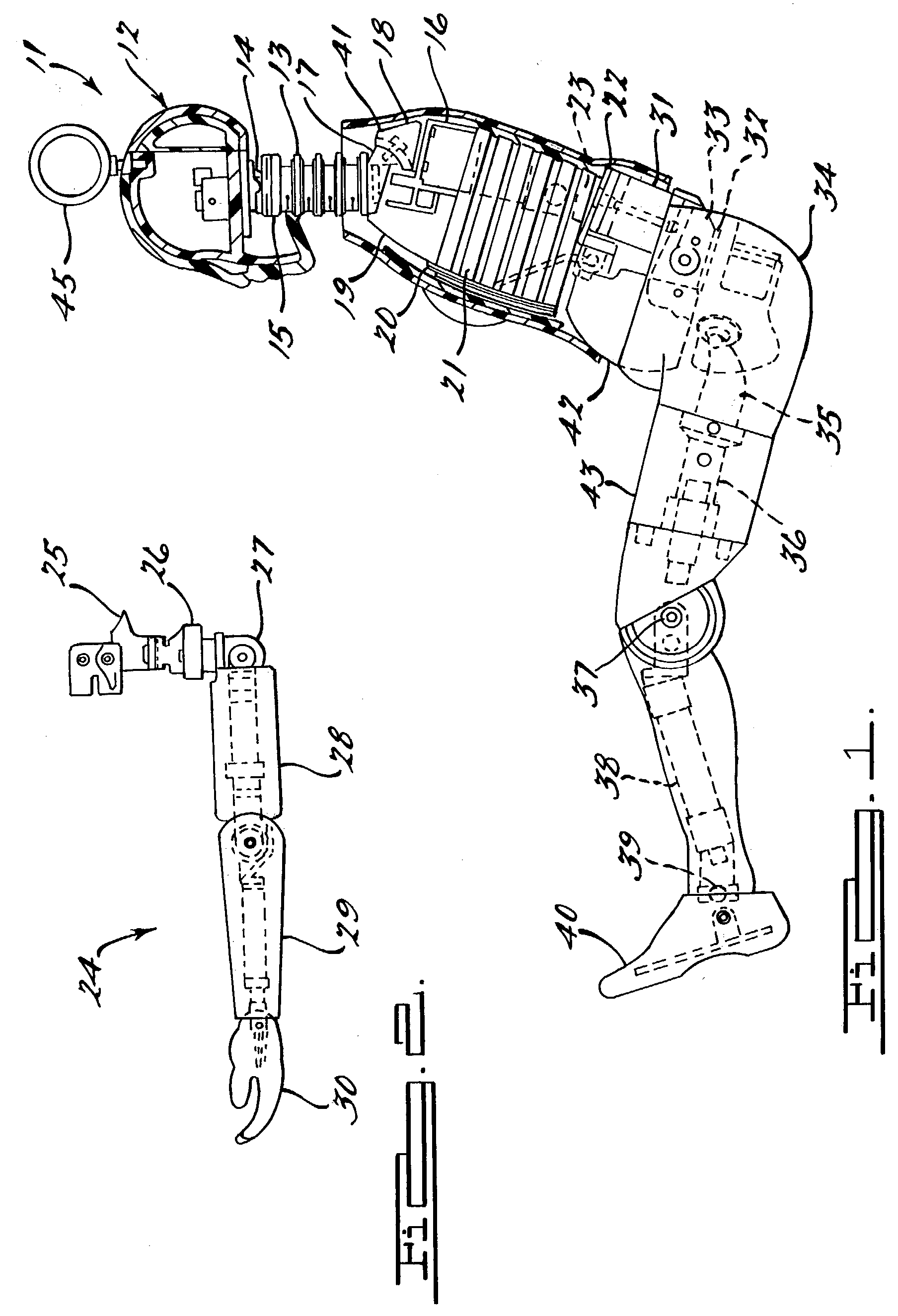
[0022] Referring to the drawings and in particular FIG. 1, one embodiment of a crash test dummy 11 of a Hybrid III fifth percentile female type is illustrated in a sitting position. This crash test dummy 11 is used primarily to test the performance of automotive interiors and restraint systems for very small adult front and rear seat occupants. The size and weight of the crash test dummy 11 are based on anthropometric studies by the Human Biomechanics and Simulation Standards Committee Task Force of the Society of Automotive Engineers and represent the lower extreme of the USA adult population. It should be appreciated that ranges of motions, centers of gravity, and segment masses simulate those of human subjects defined by the anthropometric data.

[0023] The crash test dummy 11 has a head assembly 12, which is shown in cross-section and includes a one-piece cast aluminum skull and one-piece skull cap both covered by a vinyl skin. The skull cap is removable for access to head instru...


PUM


Abstract

A measurement system is provided for a ball joint of a crash test dummy. The measurement system includes a light source operatively supported by a movable ball of the ball joint and a position sensitive detector operatively supported by a fixed member of the ball joint. The measurement system also includes a controller electrically connected to the light source to provide power to the light source for emitting light and electrically connected to the position sensitive detector that receives the emitted light to measure at least two angles between the ball and the fixed member.

Description

CROSS-REFERENCE TO RELATED APPLICATION(S)[0001] The present invention claims the priority date of copending U.S. Provisional Patent Application Serial No. 60 / 358,470, filed Feb. 21, 2002.[0002] 1. Field of the Invention[0003] The present invention relates generally to measurement systems for crash test dummies and, more specifically, to a hip joint measurement system and ankle joint measurement system for a crash test dummy.[0004] 2. Description of the Related Art[0005] It is known to provide a crash test dummy for evaluating occupant performance and occupant restraint system performance in an impact of a vehicle such as an automotive vehicle. The crash test dummy may resemble a 50.sup.th percentile male and typically includes a head, torso, arms, and legs. The crash test dummy also typically includes shoulder, elbow, and wrist joints. The crash test dummy further typically includes hip, knee, and ankle joints.[0006] It is found that the crash test dummy does not have the measuremen...

Claims


Application Information

Patent Timeline
IPC IPC(8): G01M7/08G01M17/007
CPCG01M17/0078
Inventor HUANG, YUESTANLEY, ERIC J.ELHAGEDIAB, ALI M.
Owner HUMANETICS INNOVATIVE SOLUTIONS
Why Eureka
Try Eureka