Device for measuring gas concentration

a technology for measuring devices and gas concentrations, applied in the direction of geological measurements, instruments, electrical apparatus, etc., can solve the problems of low emission efficiency in the usage area, complex electronic processing circuits used by devices, and high cost of expensive devices

Inactive Publication Date: 2004-06-10
COMMISSARIAT A LENERGIE ATOMIQUE ET AUX ENERGIES ALTERNATIVES
View PDF1 Cites 21 Cited by
  • Summary
  • Abstract
  • Description
  • Claims
  • Application Information

AI Technical Summary

Problems solved by technology

This type of device uses complex electronic processing circuits that are expensive due to the use of diodes with a very low wavelength (typically of the order of 1.65 .mu.m).
Therefore, these devices are not suitable for use in fields of application for the general public, for example such as the automotive field.
However, due to the very broad spectral width of the radiation emitted by the diodes, interference filters have to be used that result in low emission efficiency in the usage area.
Moreover, this type of interference filter is expensive.
There

Method used


Image

  • Device for measuring gas concentration
  • Device for measuring gas concentration
  • Device for measuring gas concentration

Examples


Embodiment Construction

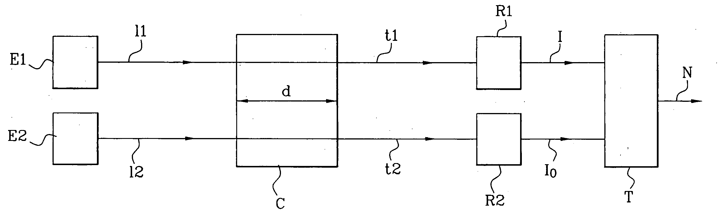
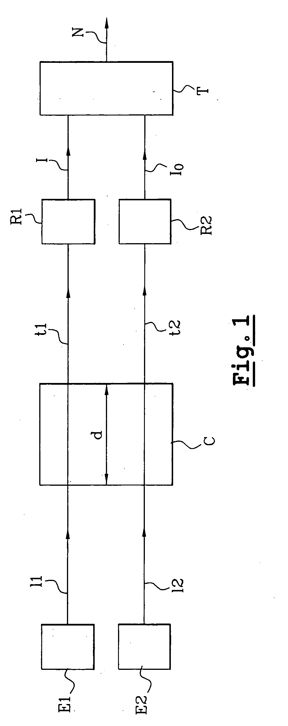
[0033] FIG. 1 shows a principle diagram of a gas concentration measurement device according to the invention. The device comprises a cavity C containing a gas for which the concentration is to be measured, a first radiation emitter E1, a second radiation emitter E2, a first reception means R1, a second reception means R2, and an electronic processing circuit T.

[0034] The emission spectrum of the emitter E1 is within the absorption band of the gas to be detected whereas the emission spectrum of the emitter E2 is outside the absorption band of the gas to be detected. Radiation 11 and 12 emitted by emitters E1 and E2 respectively pass through the cavity C over a distance d to form detected radiation t1 and t2 respectively detected by reception means R1 and R2 respectively beyond the cavity. The reception means R1 outputs a measurement I of the optical intensity of the radiation t1 and the reception means R2 outputs a measurement I.sub.0 of the optical intensity of the radiation t2. A p...


PUM


Abstract

A device for measuring the concentration of a gas contained in a cavity and for checking the operation of a catalytic element in an exhaust line in an automobile vehicle. A first emitter (E1) composed of an optical pumped micro-cavity and for which the emission spectrum is within the gas absorption band emits a first radiation that passes through the cavity. A second emitter emits a second radiation that passes through the cavity. A receptor measures the optical intensity (I) of the radiation that passed through the cavity.

Description

[0001] This application claims priority based on International Patent Application No. PCT / FR02 / 0025, entitled "Device for Measuring Gas Concentration" by Pascal Besesty, Engin Molva and Emanuel Hadji, which claims priority of French application no. 01 / 00132, filed on Feb. 18, 2002, and which was not published in English.TECHNICAL FIELD AND PRIOR ART[0002] This invention relates to a gas concentration measurement device.[0003] The invention is applicable in different fields, for example such as the analysis of gaseous industrial waste, analysis of exhaust gas from automobile vehicles, control of pure air inlet in closed containments, control of smells, etc.[0004] One particularly advantageous application of the device according to the invention in the automotive field is for checking correct operation of the catalytic element of the exhaust system of a vehicle.[0005] Different optical gas detection devices are known in prior art. For example, there are devices using laser emission di...

Claims


Application Information

Patent Timeline
IPC IPC(8): G01N21/31G01N21/35G01N21/39G01N21/53
CPCG01N21/314G01N2021/536G01N21/39G01N21/3504
Inventor BESESTY, PASCALMOLVA, ENGINHADJI, EMANUEL
Owner COMMISSARIAT A LENERGIE ATOMIQUE ET AUX ENERGIES ALTERNATIVES
Why Eureka
Try Eureka